


37
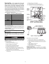
Burner Ignition —
Unit is equipped with a direct spark
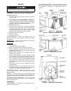
ignition 100% lockout system. Integrated Gas Unit Controller
(IGC) is located in the control box (Fig. 10). A single LED on
the IGC provides a visual display of operational or sequential
problems when the power supply is uninterrupted. The LED
can be observed through the viewport. When a break in power
occurs, the IGC will be reset (resulting in a loss of fault history)
and the evaporator fan on/off times delay will be reset. During
servicing, refer to the label on the control box cover or Table 29
for an explanation of LED error code descriptions.
If lockout occurs, unit may be reset by interrupting power
supply to unit for at least 5 seconds.
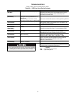
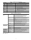
Table 29 — LED Error Code Description*
LEGEND
LED —
Light-Emitting Diode
*A 3-second pause exists between LED error code flashes. If more
than one error code exists, all applicable codes will be displayed in
numerical sequence.
†Indicates a code that is not an error. The unit will continue to oper-
ate when this code is displayed.
Main Burners —
At the beginning of each heating sea-
son, inspect for deterioration or blockage due to corrosion or
other causes. Observe the main burner flames and adjust, if
necessary.
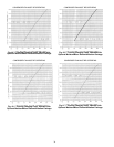
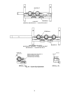
REMOVAL AND REPLACEMENT OF GAS TRAIN
(See Fig. 52 and 53)
1. Shut off manual gas valve.
2. Shut off power to unit, tag disconnect.
3. Remove compressor access panel.
4. Slide out burner compartment side panel.
5. Disconnect gas piping at unit gas valve.
6. Remove wires connected to gas valve. Mark each wire.
7. Remove induced-draft motor, ignitor, and sensor wires at
the Integrated Gas Unit Controller (IGC).
8. Remove the 2 screws that attach the burner rack to the
vestibule plate.
9. Remove the gas valve bracket.
10. Slide the burner tray out of the unit (Fig. 53).
11. To reinstall, reverse the procedure outlined above.
CLEANING AND ADJUSTMENT
1. Remove burner rack from unit as described above.
2. Inspect burners and, if dirty, remove burners from rack.
3. Using a soft brush, clean burners and cross-over port as
required.
4. Adjust spark gap. See Fig. 54.
5. Reinstall burners on rack.
6. Reinstall burner rack as described above.
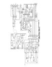
Replacement Parts —
A complete list of replace-
ment parts may be obtained from any Carrier distributor
upon request. Refer to Fig. 55 for a typical unit wiring
schematic.
LED INDICATION ERROR CODE DESCRIPTION
ON
Normal Operation
OFF
Hardware Failure
1 Flash†
Evaporator Fan On/Off Delay Modified
2 Flashes
Limit Switch Fault
3 Flashes
Flame Sense Fault
4 Flashes
4 Consecutive Limit Switch Faults
5 Flashes
Ignition Lockout Fault
6 Flashes
Induced-Draft Motor Fault
7 Flashes
Rollout Switch Fault
8 Flashes
Internal Control Fault
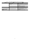
IMPORTANT: Refer to Troubleshooting Tables 30-36 for addi-
tional information.
When servicing gas train, do not hit or plug orifice spuds.
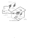
INDUCED-
DRAFT
MOTOR
MOUNTING
PLATE
INDUCED-
DRAFT
MOTOR
MANIFOLD
PRESSURE
TAP
VESTIBULE
PLATE
FLUE
EXHAUST
ROLLOUT
SWITCH
BLOWER
HOUSING
GAS
VALVE
BURNER
SECTION
Fig. 52 — Burner Section Details
Fig. 53 — Burner Tray Details