


41
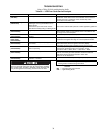
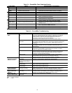
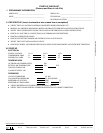
Table 33 — EconoMi$er Flash Code Identification
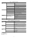
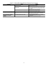
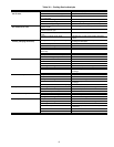
Table 34 — EconoMi$er Troubleshooting
LEGEND
FLASH CODE CAUSE ACTION TAKEN BY ECONOMI$ER
Constant On
Normal operation Normal operation.
Constant Off
No power No operation.
Continuous
Flash
CONFIG button pushed and held
between 3 and 9 seconds
Outdoor air damper is stroked fully open, then closed
(automatic test procedure takes 3 minutes to complete).
Critical Fault
Flash One
Control board fault System shutdown.
Flash Two
Thermostat fault (i.e., Y2 without Y1) System shutdown until corrected.
Flash Three
Actuator fault Revert to mechanical cooling only.
Flash Four
Supply air temperature sensor fault
Continue operation with damper at minimum position.
Revert to mechanical cooling only.
Flash Five
Outdoor air temperature sensor fault
Continue operation with damper at minimum position.
Disable mechanical cooling lockout.
Non-Critical Fault
Flash Six
Outdoor air humidity sensor fault Continue operation with dry bulb or dry bulb differential switchover.
Flash Seven
Return air temperature sensor fault
Continue operation with single enthalpy EconoMi$er
switchover or dry bulb EconoMi$er switchover (without
humidity sensor).
Flash Eight
Return air humidity sensor fault
Continue operation with single enthalpy, differential dry
bulb, or dry bulb EconoMi$er switchover.
Flash Nine
Carbon Dioxide (CO
2
) sensor fault Continue operation without ventilation control.
Flash Ten
Onboard adjustment potentiometer fault Continue operation with default potentiometer settings.
PROBLEM POTENTIAL CAUSE REMEDY
Damper Does Not
Open
Indoor (Evaporator) Fan is
Off
Check to ensure that 24 vac is present at Terminal C1 (Common Power)
on the IFC (Indoor Evaporator Fan Contactor) or that 24 vac is present at
the IFO (Indoor Evaporator Fan On) terminal. Check whether 24 vac is
present at PL 6-1 (red wire) and/or PL6-3 (black wire). If 24 vac is
not present, check wiring (see unit label diagram).
Check proper thermostat connection to G on the connection board.
No Power to EconoMi$er
Controller
Check to ensure that 24 vac is present across Terminals 24 VAC and
24 V COM on the EconoMi$er control. If 24 vac is not present, check wiring
(see unit label diagram). If 24 vac is present, STATUS light should be on
constantly.
No Power to G Terminal If IFM is on, check to ensure 24 vac is present on G Terminal of the
EconoMi$er controller. If 24 vac is not present, check wiring (see unit
label diagram).
Controller Fault If STATUS light is flashing one flash, the EconoMi$er controller is
experiencing a fault condition. Cycle power to the controller. If condition
continues, replace the EconoMi$er controller.
Thermostat Fault If STATUS light is flashing two flashes, the EconoMi$er controller senses
the thermostat is wired incorrectly. Check wiring between the thermostat
and the connection board in the electrical panel. The fault condition is
caused by Y2 being energized before Y1.
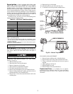
Actuator Fault Check the wiring between the EconoMi$er controller and the actuator.
Hold CONFIG button between 3 and 10 seconds to verify the
actuator’s operation. (This process takes 3 minutes to complete.)
EconoMi$er
Operation Limited to
Minimum Position
Minimum Position Set
Incorrectly
Verify that the MIN POS (%) is set greater than zero. Adjust MIN POS (%)
to 100% to verify operation, and then set to correct setting.
EconoMi$er Changeover
Set Point Set Too High or
Too Low
Set at correct value. See Table 3.
Supply Air Temperature
Sensor Faulty
If STATUS light is flashing 4 flashes, Supply Air Temperature Sensor is
faulty. Check wiring or replace sensor.
Outdoor Air Temperature
Sensor Faulty
If STATUS light is flashing 5 flashes, Outdoor Air Temperature Sensor is
faulty. Check wiring or replace sensor.
Damper Position
Less than Minimum
Position Set Point
Supply Air Low Limit
Strategy Controlling
The supply-air temperature is less than 45 F, causing the minimum
position to be decreased. Refer to the Start-Up instructions. Verify correct
setting of MIN POS (%). If correct, EconoMi$er is operating correctly.
Damper Does Not
Return to Minimum
Position
CO
2
Ventilation Strategy
Controlling
If a CO
2
sensor is being used, and the damper position is greater than
minimum position, the ventilation control strategy is controlling. Refer to
the Start-Up instructions. EconoMi$er is operating correctly.
Damper Does Not
Close on Power Loss
Damper Travel is
Restricted
Check to ensure the damper is not blocked.
IFM —
Indoor Fan Motor
PL —
Plug