


34
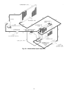
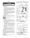
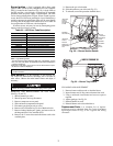
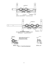
Condenser-Fan Adjustment (Fig. 43) —
Shut off
unit power supply. Remove condenser-fan assembly (grille,
motor, motor cover, and fan) and loosen fan hub setscrews.
Adjust fan height as shown in Fig. 43. Tighten setscrews and
replace condenser-fan assembly.
Economizer Adjustment —
Refer to Optional Econo-
mizer sections on pages 12 and 15.
Evaporator Fan Belt Inspection —
Check condition
of evaporator belt or tension during heating and cooling inspec-
tions or as conditions require. Replace belt or adjust as necessary.
High-Pressure Switch —
The high-pressure switch
contains a Schrader core depressor, and is located on the com-
pressor hot gas line. This switch opens at 428 psig and closes at
320 psig. No adjustments are necessary.
Loss-of-Charge Switch —
The loss-of-charge switch
contains a Schrader core depressor, and is located on the com-
pressor liquid line. This switch opens at 7 psig and closes at
22 psig. No adjustments are necessary.
Freeze-Stat —
The freeze-stat is a bimetal temperature-
sensing switch that is located on the “hair-pin” end of the evap-
orator coil. The switch protects the evaporator coil from freeze-
up due to lack of airflow. The switch opens at 30 F and closes
at 45 F. No adjustments are necessary.
Refrigerant Charge —
Amount of refrigerant charge is
listed on unit nameplate (also refer to Table 1). Refer to Carrier
GTAC2-5 Charging, Recovery, Recycling, and Reclamation
training manual and the following procedures.
Unit panels must be in place when unit is operating during
charging procedure. Unit must operate a minimum of 10 min-
utes before checking or adjusting referigerant charge.
An accurate superheat, thermocouple- or thermistor-type
thermometer, and a gage manifold are required when using the
superheat charging method for evaluating the unit charge.
Do
not use mercury or small dial-type thermometers because they
are not adequate for this type of measurement.
NO CHARGE — Use standard evacuating techniques. After
evacuating system, weigh in the specified amount of refriger-
ant. (Refer to Table 1.)
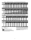
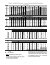
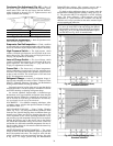
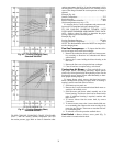
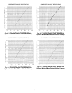
LOW CHARGE COOLING — Using Cooling Charging
Charts, Fig. 44-47, vary refrigerant until the conditions of the
charts are met. Note the charging charts are different from type
normally used. Charts are based on charging the units to the
correct superheat for the various operating conditions. Accu-
rate pressure gage and temperature sensing device are required.
Connect the pressure gage to the service port on the suction
line. Mount the temperature sensing device on the suction line
and insulate it so that outdoor ambient temperature does not af-
fect the reading. Indoor-air cfm must be within the normal op-
erating range of the unit.
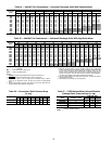
MOISTUREMISER SYSTEM CHARGING — The system
charge for units with the MoistureMiser option is greater than
that of the standard unit alone. The charge for units with this
option is indicated on the unit nameplate drawing. Also refer
to Fig. 48-51. To charge systems using the MoistureMiser
Dehumidification package, fully evacuate, recover, and re-
charge the system to the nameplate specified charge level.
To check or adjust refrigerant charge on systems using the
MoistureMiser Dehumidification package, charge per Fig. 48-
51. The subcooler MUST be energized to use the charging
charts. The charts reference a liquid pressure (psig) and
temperature at a point between the condenser coil and the
subcooler coil. A tap is provided on the unit to measure liquid
pressure entering the subcooler.
IMPORTANT: The subcooler charging charts (Fig. 48-
51) are to be used ONLY with units having the optional
MoistureMiser subcooling option. DO NOT use standard
charge (Fig. 44-47) for units with MoistureMiser option,
and DO NOT use Fig. 48-51 for standard units.
Fig. 43 — Condenser-Fan Adjustment
UNIT 48HJ FAN HEIGHT — “A” (in.)
004-006 and 007 (208/230 V)
2.75
007 (460 and 575 V)
3.50
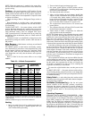
Fig. 45 — Cooling Charging Chart,
Standard 48HJ005
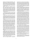
Fig. 44 — Cooling Charging Chart,
Standard 48HJ004