


30
NOTE: When the compressor is rotating in the wrong direc-
tion, the unit will make an elevated level of noise and will not
provide cooling.
Cooling —
Set space thermostat to OFF position. To start
unit, turn on main power supply. Set system selector switch at
COOL position and fan switch at AUTO. position. Adjust ther-
mostat to a setting below room temperature. Compressor starts
on closure of contactor.
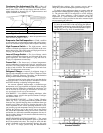
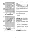
Check unit charge. Refer to Refrigerant Charge section on
page 34.
Reset thermostat at a position above room temperature.
Compressor will shut off. Evaporator fan will shut off after a
30-second delay.
TO SHUT OFF UNIT — Set system selector switch at OFF
position. Resetting thermostat at a position above room tem-
perature shuts unit off temporarily until space temperature ex-
ceeds thermostat setting. Units are equipped with Cycle-
LOC™ protection device. Unit shuts down on any safety trip,
and indicator light on thermostat comes on. Check reason for
all safety trips.
Compressor restart is accomplished by manual reset at the
thermostat by turning the selector switch to OFF and then to
ON position.
Main Burners —
Main burners are factory set and should
require no adjustment.
TO CHECK ignition of main burners and heating controls,
move thermostat set point above room temperature and verify
that the burners light and evaporator fan is energized. Check
heating effect, then lower the thermostat setting below the
room temperature and verify that the burners and evaporator
fan turn off.
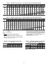
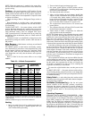
Refer to Table 28 for the correct orifice to use at high
altitudes.
Table 28 — Altitude Compensation*
*As the height above sea level increases, there is less oxygen per
cubic foot of air. Therefore, heat input rate should be reduced at
higher altitudes.
†Orifices available through your local Carrier distributor.
Heating
1. Purge gas supply line of air by opening union ahead of
the gas valve. If gas odor is detected, tighten union and
wait 5 minutes before proceeding.
2. Turn on electrical supply and manual gas valve.
3. Set system switch selector at HEAT position and fan
switch at AUTO. or ON position. Set heating temperature
lever above room temperature.
4. The induced-draft motor will start.
5. After a call for heating, the main burners should light
within 5 seconds. If the burner does not light, then there is
a 22-second delay before another 5-second try. If the
burner still does not light, the time delay is repeated. If the
burner does not light within 15 minutes, there is a lock-
out. To reset the control, break the 24 v power to W1.
6. The evaporator-fan motor will turn on 45 seconds after
burner ignition.
7. The evaporator-fan motor will turn off in 45 seconds after
the thermostat temperature is satisfied.
8. Adjust airflow to obtain a temperature rise within the
range specified on the unit nameplate.
NOTE: The default value for the evaporator-fan motor on/off
delay is 45 seconds. The Integrated Gas Unit Controller (IGC)
modifies this value when abnormal limit switch cycles occur.
Based upon unit operating conditions, the on delay can be
reduced to 0 seconds and the off delay can be extended to
180 seconds. When one flash of the LED (light-emitting diode)
is observed, the evaporator-fan on/off delay has been modified.
If the limit switch trips at the start of the heating cycle dur-
ing the evaporator on delay, the time period of the on delay for
the next cycle will be 5 seconds less than the time at which the
switch tripped. (Example: If the limit switch trips at 30 sec-
onds, the evaporator-fan on delay for the next cycle will occur
at 25 seconds.) To prevent short-cycling, a 5-second reduction
will only occur if a minimum of 10 minutes has elapsed since
the last call for heating.
The evaporator-fan off delay can also be modified. Once the
call for heating has ended, there is a 10-minute period during
which the modification can occur. If the limit switch trips dur-
ing this period, the evaporator-fan off delay will increase by
15 seconds. A maximum of 9 trips can occur, extending the
evaporator-fan off delay to 180 seconds.
To restore the original default value, reset the power to the
unit.
TO SHUT OFF UNIT — Set system selector switch at off po-
sition. Resetting heating selector lever below room temperature
will temporarily shut unit off until space temperature falls be-
low thermostat setting.
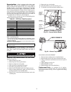
Safety Relief —
A soft-solder joint at the suction service
Schrader port provides pressure relief under abnormal tempera-
ture and pressure conditions.
Ventilation (Continuous Fan) —
Set fan and system
selector switches at ON and OFF positions, respectively.
Evaporator fan operates continuously to provide constant air
circulation. When the evaporator-fan selector switch is turned
to the OFF position, there is a 30-second delay before the fan
turns off.
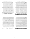
Operating Sequence
COOLING, UNITS WITHOUT ECONOMIZER — When
thermostat calls for cooling, terminals G and Y1 and the com-
pressor contactor (C) are energized. The indoor (evaporator) fan
motor (IFM), compressor, and outdoor (condenser) fan motor
(OFM) start. The OFM runs continuously while the unit is in
cooling. When the thermostat is satisfied, C is deenergized and
the compressor and OFM shut off. After a 30-second delay, the
(IFM) shuts off. If the thermostat fan selector switch is in the
ON position, the evaporator motor will run continuously.
ELEVATION
(ft)
72,000 AND 115,000
BTUH NOMINAL
INPUT
150,000 BTUH
NOMINAL INPUT
Natural
Gas
Orifice
Size†
Liquid
Propane
Orifice
Size†
Natural
Gas
Orifice
Size†
Liquid
Propane
Orifice
Size†
0-2,000
33 43 30 38
2,000
34 43 30 39
3,000
35 44 31 40
4,000
36 44 32 41
5,000
36 44 33 42
6,000
37 45 34 43
7,000
37 45 35 43
8,000
38 46 36 44
9,000
39 47 37 44
10,000
41 48 38 45
11,000
43 48 39 45
12,000
44 49 40 46
13,000
44 49 41 47
14,000
45 50 42 47