


12
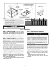
OPTIONAL DURABLADE ECONOMIZER — The option-
al economizer hood assembly is packaged and shipped in the
filter section. Damper blades and control boards are installed at
the factory and the economizer is shipped in the vertical dis-
charge position.
NOTE: Horizontal discharge block-off plate is shipped with
the air hood package. If unit is to be used for vertical discharge
application, discard this plate.
Assembly:
1. Determine if ventilation air is required in building. If so,
determine the minimum amount to be supplied by each
unit and record quantity of ventilation air needed for use
in Step 7.
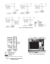
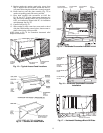
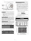
2. Remove filter access panel by raising panel and swinging
panel outward. Panel is now disengaged from track and
can be removed. No tools are required to remove filter ac-
cess panel. Remove outdoor-air opening panel. Save pan-
els and screws. See Fig. 13. Remove economizer, and re-
move optional outdoor-air damper hood package from
filter section (located behind economizer).
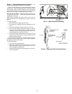
3. Assemble outdoor-air hood top and side plates as shown
in Fig. 14. Install seal strips on hood top and sides. Put
aside screen retainer and retainer screw for later assem-
bly.
Do not attach hood to unit at this time.
4. Slide economizer into unit and secure with screws. See
Fig. 15.
NOTE: Be sure to engage rear economizer flange under
tabs in vertical return-air opening.
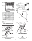
5. To convert to horizontal discharge application:
a. Rotate economizer 90 degrees until the econo-
mizer motor faces the condenser section (see
Fig. 16).
b. Remove tape and shipping screw, rotate the baro-
metric relief damper cover 90 degrees.
c. Install horizontal discharge block-off plate over
the opening on the access panel. (Block-off plate
MUST be installed before installing hood assem-
bly.) See Fig. 17.
6. Remove 12-pin blue and yellow wire jumper plug from
factory wiring harness and store. Insert economizer plug
into 12-pin plug of factory wiring harness. Remove tape
and shipping screw from barometric relief damper. See
Fig.18.
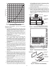
7. If ventilation air is not required, proceed to Step 8. If ven-
tilation air is required, determine minimum position set-
ting for required airflow. See Fig. 19. Adjust minimum
position setting by adjusting the screws on the position
setting bracket. Slide bracket until the top screw is in the
position determined by Fig. 19. Tighten screws.
8. Remove tape from outdoor-air thermostat (OAT). Fasten
OAT to inside of hood using screws and speed clips pro-
vided. See Fig. 20. Make sure OAT terminals are posi-
tioned up.
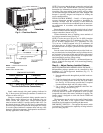
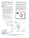
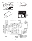
MOISTUREMISER
% RELATIVE HUMIDITY
Fig. 11 — Accessory Field-Installed Humidistat
LEGEND
C —
Contactor (Compressor)
CCH —
Crankcase Heater
COMP —
Compressor
FU —
Fuse
HU —
Humidistat
IFM —
Indoor (Evaporator) Fan Motor
LLSV —
Liquid Line Solenoid Valve
S-LPS —
Low-Pressure Switch (Subcooler Only)
TRAN —
Transformer
Factory Wiring
Accessory or Optional Wiring
Fig. 12 — Typical MoistureMiser Dehumidification Package Humidistat Wiring
(208/230-V Unit Shown)