


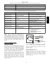

45
Table 10 – LEDs
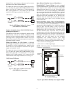
The LEDs on the RTU Open Control Board (see Fig. 57) show the status of certain functions:
If this LED is on... Status is...
Power RTU Open has power
Rx RTU Open is receiving d ata from the network segment
Tx RTU Open is transmitting data over th e network segment
DO# The digital output is active
The Run and Error LEDs indicate control module and network status
If R un LED shows...
And Error LED show s... Status is...
2 flashes per second Off Normal
2 flashes per second
2flashes,
alternating with Run LED
Five minute auto---restart delay after system error
2 flashes per second
3flashes,
then off
Control module has just been formatted
2 flashes per second
4flashes,
then pause
Two or more devices on this network have t he
same ARC156 network address
2 flashes per second On
Exec halted a fter frequent system erro rs or
control programs halted
5 flashes per second On Exec start---up aborted, Boot is running
5 flashes per second Off Firmware transfer in progress, Boot is running
7 flashes per second
7 flashes per second, alternating w ith
Run LED
Ten second recovery period after brownout
14 flashes per second
14 flashes per second,
alternating with Run LED
Brownout
On On
Failure. Try the following solutions:
S TurnRTUOpenoff,thenon.
S Format RTU Open.
S Download memory to RTU Open.
S Replace RTU Open.
NOTE: Refer to Catalog No. 48--50HCTQ--01T for
complete configuration of RTU Open, operating sequences
and troubleshooting information. Refer to RTU Open
Controller Integration Guide (Catalog No. 11--808--428--01)
for details on configuration and troubleshooting of connected
networks. Have a copy of these manuals available at unit
start--up.
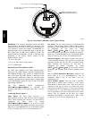
Outdoor Air Enthalpy Control
(PNO
33CSENTHSW)
The enthalpy control (33CSENTHSW) is available as a
field--installed accessory to be used with the EconoMi$er2
damper system. The outdoor air enthalpy sensor is part of
the enthalpy control. (The separate field--installed
accessory return air enthalpy sensor (33CSENTSEN) is
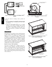
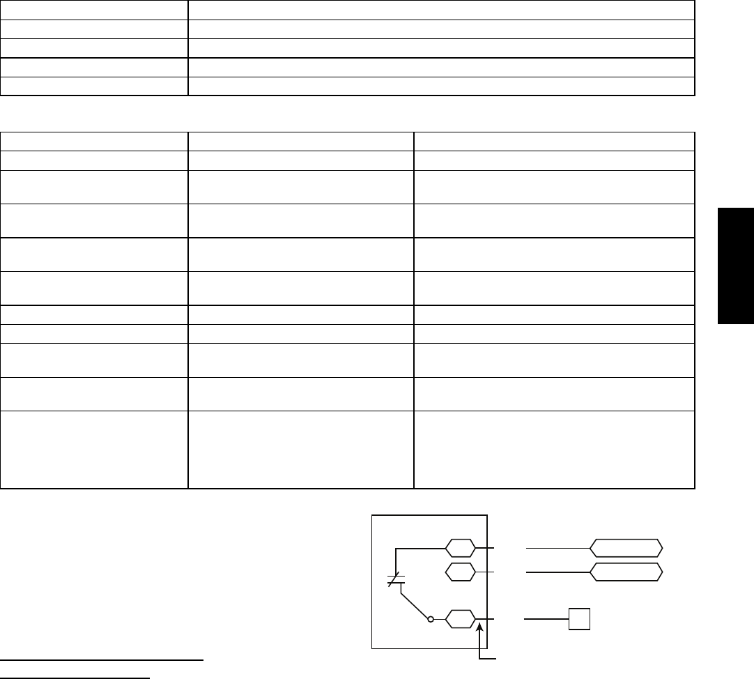
required for differential enthalpy control. See Fig. 71.)
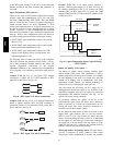
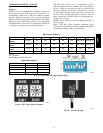
Locate the enthalpy control in the economizer next to the
Actuator Motor. Locate two GRA leads in the factory
harness and connect the gray lead labeled “ESL” to the
terminal labeled “LOW”. See Fig. 71. Connect the
enthalpy control power input terminals to economizer
actuator power leads RED (connect to 24V) and BLK
(connect to GND).
7
CTB ECON
(P’LINK: to J4-2) or
(RTU Open: to J2-6)
LOW
GND
24V
Enthalpy
Switch
GRA
BLK
RED
Factory Wiring Harness
PL6-1 (24-V)
PL6-4 (COM)
C11160
Fig. 71 -- Enthalpy Switch (33CSENTHSW) Connections
The outdoor enthalpy changeover setpoint is set at the
enthalpy controller.
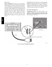
Differential Enthalpy Control —
Differential enthalpy control is provided by sensing and
comparing the outside air and return air enthalpy
conditions. Install the outdoor air enthalpy control as
described above. Add and install a return air enthalpy
sensor (see Fig. 72).
48HC