


18
Factory--Option Thru--Base Connections —
Electrical Connections: Knockouts are located in the
control box area. Remove the appropriate size knockout
for high voltage connection. Use the field supplied
connector depending on wiring or conduit being utilized.
Remove the
7
/
8
--in (22mm) knockout and appropriate
connector for low voltage wiring. If non--unit powered
convenience outlet is being utilized, remove the
7
/
8
-- i n
(22mm) knockout and utilize appropriate connector for
115 volt line. See “Step 12 — Making Electrical
Connections” for details.
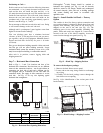
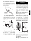
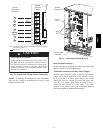
Gas Connections: Remove the knockout in the base pan
and route
3
/
4
--in. gas line up through the opening. Install
an elbow and route gas line through opening in panel after
first removing plastic bushing. Install a gas shut off
followed by a drip leg and ground--joint union. Route gas
line into gas section through the grommet (Part #:
KA56SL112) at the gas inlet and into the gas valve. See
Fig. 17 and Table 2. If a regulator is installed, it must be
located 4 feet (1.22 meters) from the flue outlet.
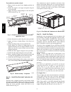
Some municipal codes require that the manual shutoff
valve be located upstream of the sediment trap. See
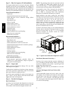
Fig. 18 for typical piping arrangements for gas piping that
has been routed through the sidewall of the base pan.
When installing the gas supply line, observe local codes
pertaining to gas pipe installations. Refer to the NFPA
54/ANSI Z223.1 NFGC latest edition (in Canada, CAN/CSA
B149.1). In the absence of local building codes, adhere to
the following pertinent recommendations:
1. Avoid low spots in long runs of pipe. Grade all pipe
1
/
4
--in. in every 15 ft (7 mm in every 5 m) to prevent
traps. Grade all horizontal runs downward to risers.
Use risers to connect to heating section and to meter.
2. Protect all segments of piping system against physical
and thermal damage. Support all piping with appro-
priate straps, hangers, etc. Use a minimum of one
hanger every 6 ft (1.8 m). For pipe sizes larger than
1
/
2
--in., follow recommendations of national codes.
3. Apply joint compound (pipe dope) sparingly and only to
male threads of joint when making pipe connections.
Use only pipe dope that is resistant to action of lique-
fied petroleum gases as specified by local and/or nation-
al codes. If using PTFE (Teflon) tape, ensure the materi-
al is Double Density type and is labeled for use on gas
lines. Apply tape per manufacturer’s instructions.
4. Pressure--test all gas piping in accordance with local
and national plumbing and gas codes before connect-
ing piping to unit.
NOTE: Pressure test the gas supply system after the gas
supply piping is connected to the gas valve. The supply
piping must be disconnected from the gas valve during the
testing of the piping systems when test pressure is in
excess of 0.5 psig (3450 Pa). Pressure test the gas supply
piping system at pressures equal to or less than 0.5 psig
(3450 Pa). The unit heating section must be isolated from
the gas piping system by closing the external main manual
shutoff valve and slightly opening the ground--joint union.
Check for gas leaks at the field--installed and
factory--installed gas lines after all piping connections have
been completed. Use soap--and--water solution (or method
specified by local codes and/or regulations).
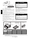
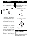
FIRE OR EXPLOSION HAZARD
Failure to follow this warning could result in personal
injury, death and/or property damage.
S Connect gas pipe to unit using a backup wrench to
avoid damaging gas controls.
S Never purge a gas line into a combustion chamber.
S Never test for gas leaks with an open flame. Use a
commercially available soap solution made
specifically for the detection of leaks to check all
connections.
S Use proper length of pipe to avoid stress on gas
control manifold.
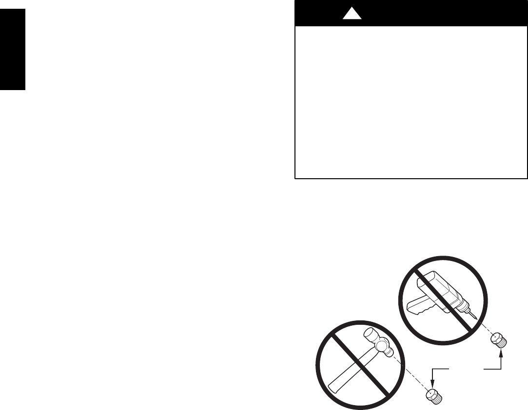
!
WARNING
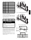
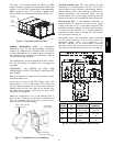
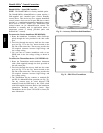
NOTE: If orifice hole appears damaged or it is suspected to
have been redrilled, check orifice hole with a numbered drill
bit of correct size. Never redrill an orifice. A burr--free and
squarely aligned orifice hole is essential for proper flame
characteristics.
BURNER
ORIFICE
A93059
Fig. 20 -- Orifice Hole
48HC