


15
PositioningonCurb—
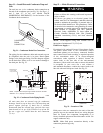
Position unit on roof curb so that the following clearances
are maintained:
1
/
4
in. (6 mm) clearance between the roof
curb and the base rail inside the right and left,
1
/
2
in.
(12 mm) clearance between the roof curb and the base rail
inside the front and back. This will result in the distance
between the roof curb and the base rail inside on the
condenser end of the unit being approximately equal to
Details A and B in Figs. 6, 7 and 8.
Do not attempt to slide unit on curb after unit is set. Doing
so will result in damage to the roof curb seal.
Although unit is weatherproof, guard against water from
higher level runoff and overhangs.
Flue vent discharge must have a minimum horizontal
clearance of 48 in. (1220 mm) from electric and gas meters,
gas regulators, and gas relief equipment. Minimum distance
between unit and other electrically live parts is 48 inches
(1220 mm).
Flue gas can deteriorate building materials. Orient unit such
that flue gas will not affect building materials. Locate
mechanical draft system flue assembly at least 48 in. (1220
mm) from an adjacent building or combustible material.
After unit is in position, remove rigging skids and
shipping materials.
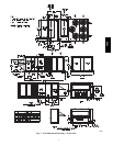
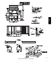
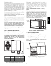
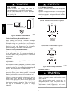
Step 7 — Horizontal Duct Connection
Refer to Figs. 1, 2 and 3 for locations and sizes of the
horizontal duct connections. Note that there are two different
return air duct connection locations – one for unit without an
economizer (on back side of unit) and a different one for
unit equipped with an economizer (on left end, under the
economizer hood). The supply air duct connection is on the
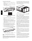
back side. See Fig. 11 for top view depicting typical
horizontal duct arrangements.
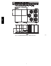
Return Air Duct
with Economize
r
Return Air Duct
without
Economizer
Horizontal
Supply Air
C10626
Supply
Return without
Economizer
Return with
Economizer
Location Back Back Left end
Height --- In. (mm) 15
7
/
8
(402) 49
3
/
8
(1253) 18
3
/
8
(467)
Width --- in. (mm) 29
3
/
4
(756) 23
3
/
8
(593) 61
5
/
8
(1564)
Fig. 11 -- Horizontal Duct Opening Dimensions
Field--supplied
(3
/
4
--inch) flanges should be attached to
horizontal duct openings (see Fig. 11) and all ductwork
should be secured to the flanges. Insulate and weatherproof
all external ductwork, joints, and roof or building openings
with counter flashing and mastic in accordance with
applicable codes.
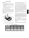
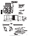
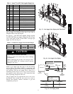
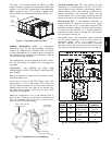
Step 8 — Install Outside Air Hood — Factory
Option
The outside air hood for factory--option economizer and
two--position damper is shipped in knock--down form and
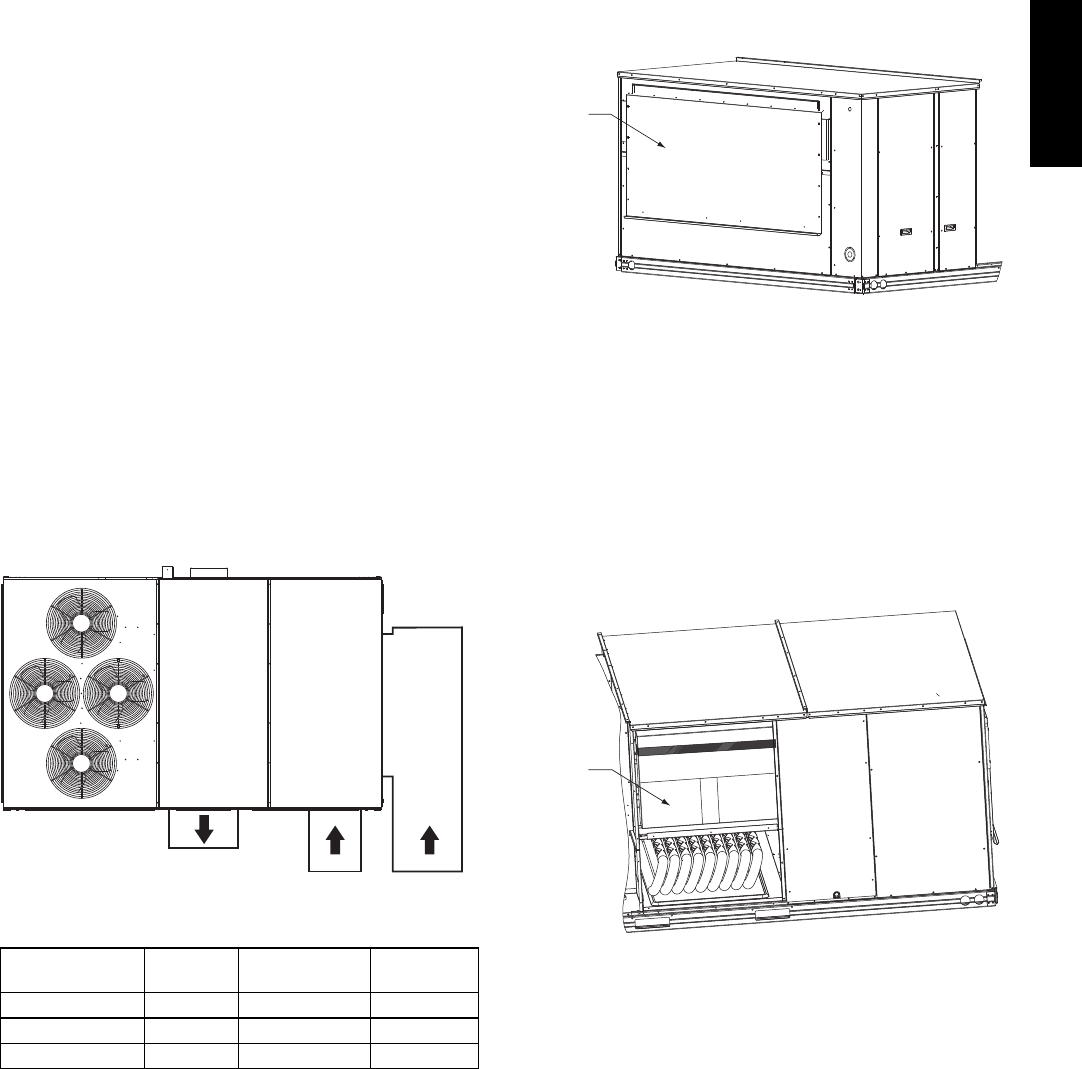
requires field assembly. The panel for the hood top is
shipped on the end of the unit (see Fig. 12). The
remaining parts for the hood assembly (including side
panels, filters and tracks) are shipped in a carton that is
secured to the rear of the blower assembly. Access the
carton location through rear panel (see Fig. 13).
Hood Top
Shipping
Position
C09134
Fig. 12 -- Hood Top – Shipping Position
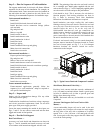
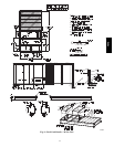
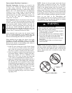
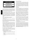
To remove the hood parts package:
1. Remove the back blower access panel.
2. Locate and cut the strap, being careful to not damage
any wiring.
3. Carefully lift the hood package carton through the
back blower access opening.
See Fig. 14 for identification of the various parts of the
hood assembly.
Hood
Package
C09133
Fig. 13 -- Hood Package – Shipping Location
48HC