


19
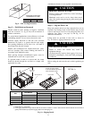
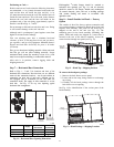
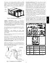
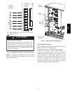
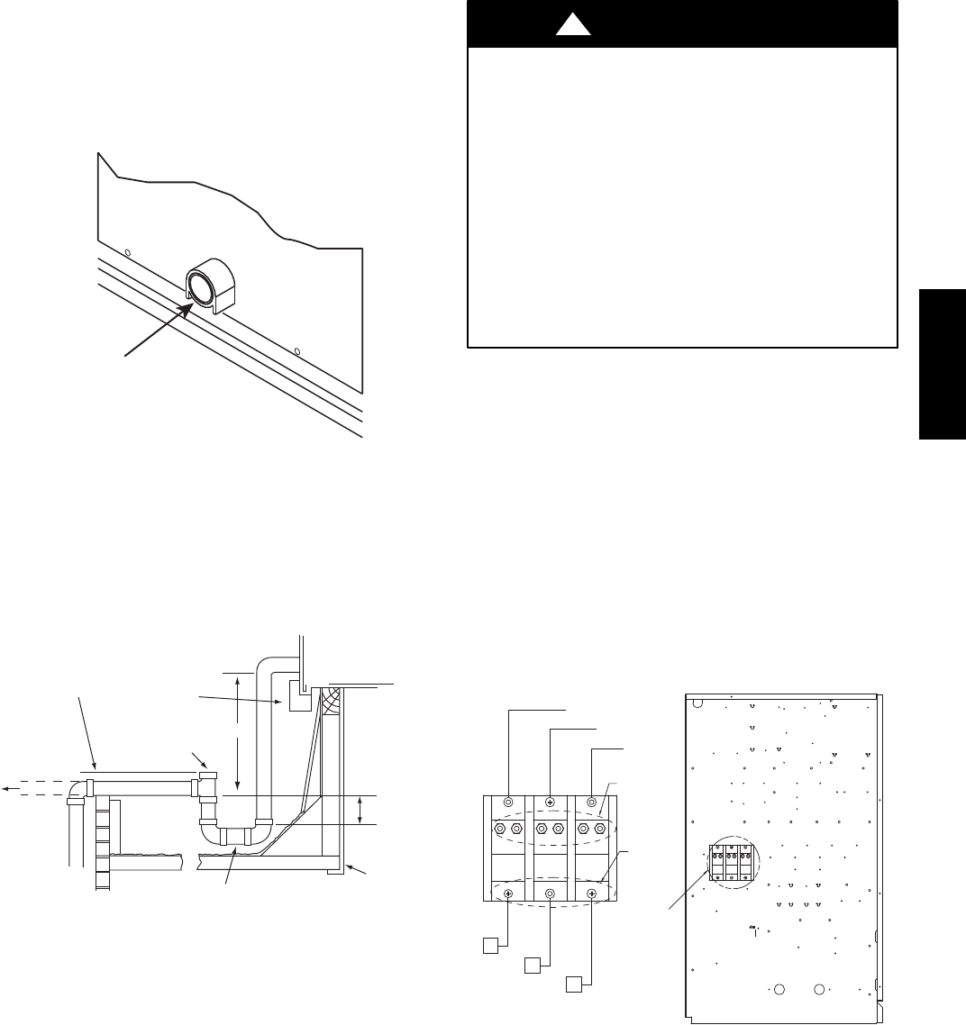
Step 11 — Install External Condensate Trap and
Line
The unit has one
3
/
4
-in. condensate drain connection on
the end of the condensate pan (see Fig. 21). See Figs. 1, 2
and 3, item “E”, in the view labeled “BACK
(HORIZONTAL DISCHARGE)” for the location of the
condensate drain connection.
CONDENSATE
DRAIN
CONNECTION
C10729
Fig. 21 -- Condensate Drain Pan Connection
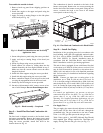
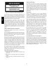
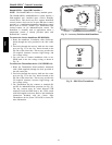
The piping for the condensate drain and external trap can
be completed after the unit is in place. Hand tighten
fittings to the drain pan fitting. Provide adequate support
for the drain line. Failure to do so can result in damage to
the drain pan. See Fig. 22.
NOTE: Trap should be deep enough to offset maximum unit static
difference. A 4” (102) trap is recommended.
MINIMUM PITCH
1” (25mm) PER
10’ (3m) OF LINE
BASE RAIL
OPEN
VENT
TO ROOF
DRAIN
DRAIN PLUG
ROOF
CURB
SEE NOTE
2˝ (51) MIN
C08022
Fig. 22 -- Condensate Drain Piping Details
All units must have an external trap for condensate
drainage. Install a trap at least 4-in. (102 mm) deep and
protect against freeze-up. If drain line is installed
downstream from the external trap, pitch the line away
from the unit at 1-in. per 10 ft (25 mm in 3 m) of run. Do
not use a pipe size smaller than the unit connection
(
3
/
4
-in.).
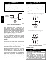
Step 12 — Make Electrical Connections
ELECTRICAL SHOCK HAZARD
Failure to follow this warning could result in personal
injury or death.
Do not use gas piping as an electrical ground. Unit
cabinet must have an uninterrupted, unbroken electrical
ground to minimize the possibility of personal injury if
an electrical fault should occur. This ground may consist
of electrical wire connected to unit ground lug in control
compartment, or conduit approved for electrical ground
when installed in accordance with NEC (National
Electrical Code); ANSI/NFPA 70, latest edition (in
Canada, Canadian Electrical Code CSA [Canadian
Standards Association] C22.1), and local electrical
codes.
!
WARNING
NOTE: Field--supplied wiring shall conform with the
limitations of minimum 63_F(33_C) rise.
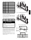
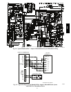
Field Power Supply —
If equipped with optional Powered Convenience Outlet:
The power source leads to the convenience outlet’s
transformer primary are not factory connected. Installer
must connect these leads according to required operation
of the convenience outlet. If an always--energized
convenience outlet operation is desired, connect the
source leads to the line side of the unit--mounted
disconnect. (Check with local codes to ensure this method
is acceptable in your area.) On a unit without a
unit--mounted disconnect, connect the source leads to the
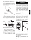
line side with unit field power leads. See Fig. 23.
LOAD
SIDE
SEE
DETAIL
A
DETAIL
A
LINE
SIDE
BLK
YEL
BLU
CONTROL BOX
L3
L2
L1
C11181
Fig. 23 -- Location of TB1
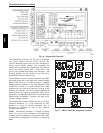
Field power wires are connected to the unit at line--side
pressure lugs on the terminal block (see wiring diagram
label for control box component arrangement) or at
factory--installed option non--fused disconnect switch. Use
copper conductors only.
NOTE: Make field power connections directly to line
connection pressure lugs only.
48HC