


23
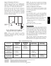
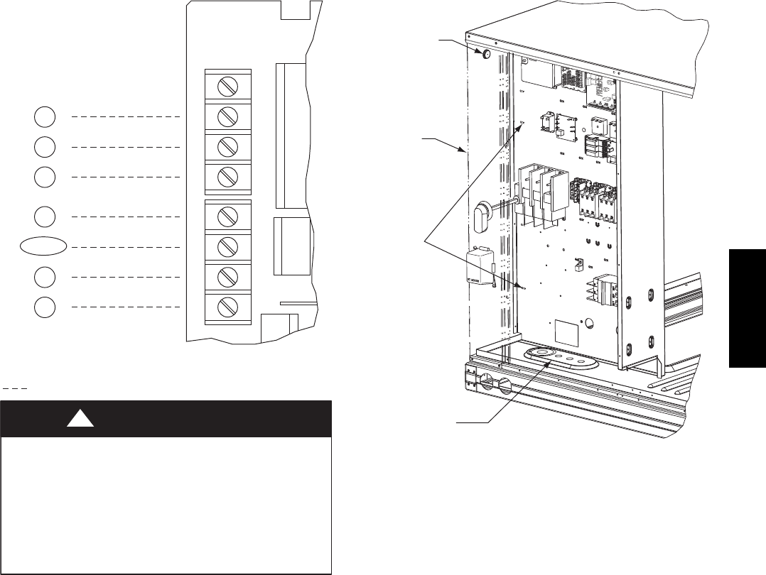
C
W2
G
W1
R
Y1
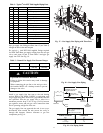
Typical
Thermostat
Corrections
O/B/Y2
(see Note)
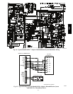
Note: Typical multi-function marking. Follow manufacturer’s configuration
instructions to select Y2.
Field Wiring
Central
Terminal
Board
W1
Y2
Y1
R
W2
G
C
X
W1
Y2
Y1
R
W2
G
C
X
T–STAT
See
Caution
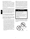
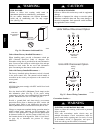
UNIT DAMAGE HAZARD
Failure to follow this caution may cause a short circuit.
CAUTION
!
Carefully check the connection of control coductor
for indoor fan control at terminal G. Connecting the
indoor fan lead to terminal C will cause a short circuit
condition which can cause component damage inside
the unit or at thermostat.
C10731
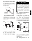
Fig. 30 -- Typical Low--Voltage Control Connections
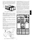
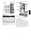
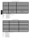
NOTE: If utilizing the through the base connections,
route the low voltage wire through the wire ties to the
central terminal board.
Rubber
Grommet
Corner
Post
Wire
Ties
Thru the Base
Connection
C10734
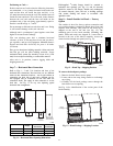
Fig. 31 -- Field Control Wiring Raceway
Heat Anticipator Settings —
Set heat anticipator settings at 0.14 amp for the first stage
and 0.14 amp for second--stage heating.
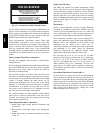
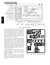
Transformer Connection for 208--v Power Supply —
All units except 208/230-v units are factory wired for the
voltage shown on the nameplate. If the 208/230-v unit is
to be connected to a 208-v power supply, the control
transformer must be rewired by moving the black wire
with the
1
/
4
-in. female spade connector from the 230--v
connection and moving it to the 208-v
1
/
4
-in. male
terminal on the primary side of the transformer. Refer to
unit label diagram for additional information.
48HC