


10
Step 2 — Plan for Sequence of Unit Installation
The support method used for this unit will dictate different
sequences for the steps of unit installation. For example, on
curb--mounted units, some accessories must be installed on
the unit before the unit is placed on the curb. Review the
following for recommended sequences for installation steps.
Curb--mounted installation —
Install curb
Install field--fabricated ductwork inside curb
Install thru--base service connection fittings (affects
curb and unit)
Rig and place unit
Remove top skid
Install outside air hood
Install smoke detector tube
Install combustion air hood
Install flue hood
Install gas piping
Install condensate line trap and piping
Make electrical connections
Install other accessories
Pad--mounted installation —
Prepare pad and unit supports
Rig and place unit
Remove duct covers and top skid
Install smoke detector return air sensor tube
Install field--fabricated ductwork at unit duct openings
Install outside air hood
Install combustion air hood
Install flue hood
Install gas piping
Install condensate line trap and piping
Make electrical connections
Install other accessories
Frame--mounted installation —
Frame--mounted applications generally follow the
sequence for a curb installation. Adapt as required to
suit specific installation plan.
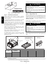
Step 3 — Inspect unit
Inspect unit for transportation damage. File any claim
with transportation agency.
Confirm before installation of unit that voltage, amperage
and circuit protection requirements listed on unit data
plate agree with power supply provided.
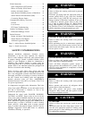
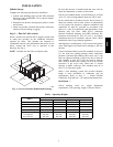
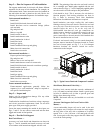
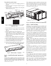
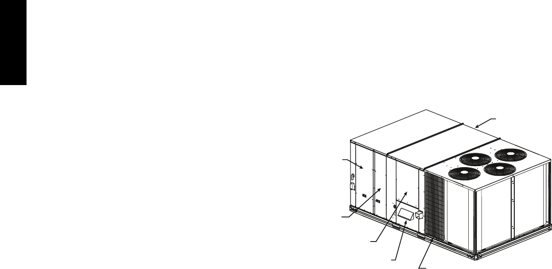
Locate the carton containing the outside air hood parts; see
Figs. 5 and 12. Do not remove carton until unit has been
rigged and located in final position.
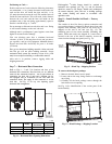
Step 4 — Provide Unit Support
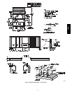
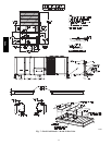
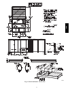
Roof Curb Mount —
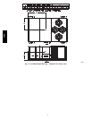
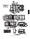
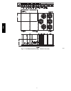
Accessory roof curb details and dimensions are shown in
Figs. 6, 7 and 8. Assemble and install accessory roof curb
in accordance with instructions shipped with the curb.
NOTE: The gasketing of the unit to the roof curb is critical
for a watertight seal. Install gasket supplied with the roof
curb as shown in Figs. 6, 7 and 8. Improperly applied gasket
can also result in air leaks and poor unit performance.
Curb should be level. This is necessary for unit drain to
function properly. Unit leveling tolerances are show in
Fig. 9. Refer to Accessory Roof Curb Installation
Instructions for additional information as required.
Install insulation, cant strips, roofing felt, and counter
flashing as shown. Ductwork must be attached to curb and
not to the unit. Thru--the--base power connection must be
installed before the unit is set on the roof curb. If
field--installed thru--the--roof curb gas connections are
desired remove knockout in basepan located in the gas
section, see Fig. 5 for location. Gas connections and
power connections to the unit must be field installed after
the unit is installed on the roof curb.
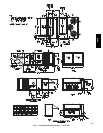
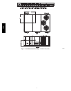
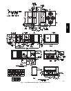
If electric and control wiring is to be routed through the
basepan, remove knockouts in basepan located in control
box area of access panel; see Fig. 1, 2, or 3 for basepan
knockout locations for location. Attach the service
connections to the basepan.
Control Box
A
ccess Panel
Filter and
Indoor Coil
Access Panel
Indoor Blower
Access Panel
Gas Heat
Access Panel
Compressor
(each side)
Hood Carton Location
(rear access panel)
C11154
Fig. 5 -- Typical Access Panel and Compressor Locations
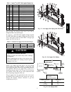
Slab Mount (Horizontal Units Only) —
Provide a level concrete slab that extends a minimum of
6–in. (150 mm) beyond unit cabinet. Install a gravel apron
in front of condenser coil air inlet to prevent grass and
foliage from obstructing airflow.
NOTE: Horizontal units may be installed on a roof curb
if required.
Alternate Unit Support (In Lieu of Curb or Slab
Mount) —
A non--combustible sleeper rail can be used in the unit
curb support area. If sleeper rails cannot be used, support
the long sides of the unit with a minimum of 4 equally
spaced 4--in. x 4--in. (102 mm x 102 mm) pads on each
side. Locate pads so that they support the rails. Make sure
to avoid the fork openings.
48HC