


21
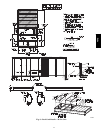
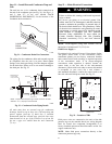
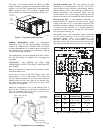
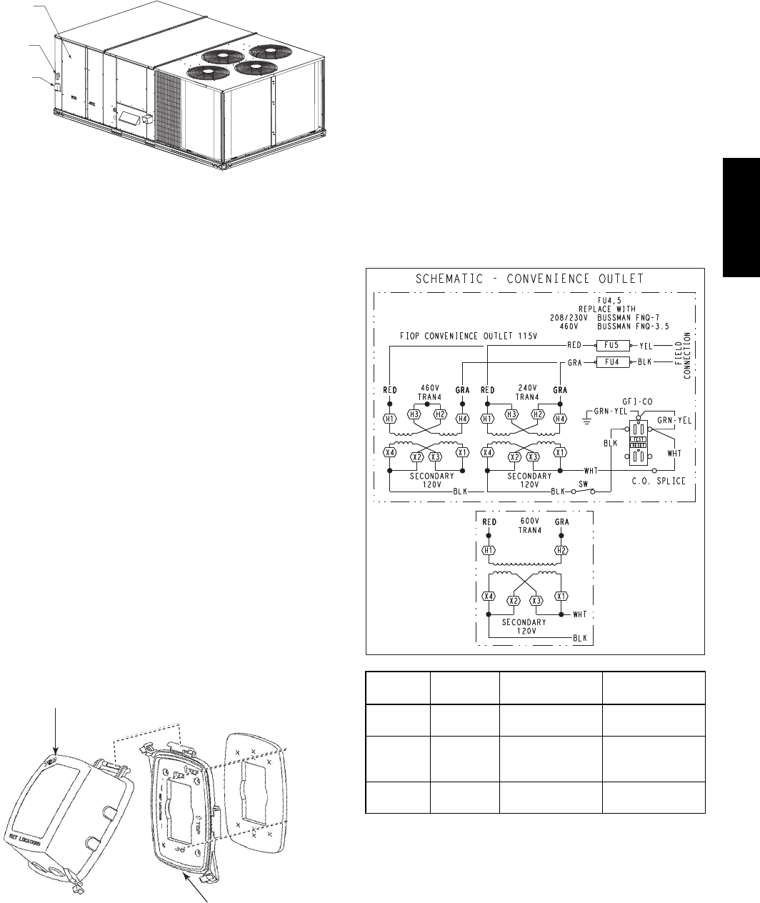
Two types of convenience outlets are offered on 48HC
models: Non--unit powered and unit--powered. Both types
provide a 125--volt GFCI (ground--fault circuit--interrupter)
duplex receptacle rated at 15--A behind a hinged access
cover, located on the corner panel of the unit. See Fig. 26.
Convenience
Outlet
Electric
Disconnect
Switch
Control Box
Access Panel
C10641
Fig. 26 -- Convenience Outlet Location
Installing Weatherproof Cover: A weatherproof
while-in-use cover for the factory-installed convenience
outlets is now required by UL standards. This cover cannot
be factory-mounted due to its depth; it must be installed at
unit installation. For shipment, the convenience outlet is
covered with a blank cover plate.
The weatherproof cover kit is shipped in the unit’s control
box. The kit includes the hinged cover, a backing plate
and gasket.
DISCONNECT ALL POWER TO UNIT AND
CONVENIENCE OUTLET. LOCK--OUT AND TAG--OUT
ALL POWER.
Remove the blank cover plate at the convenience outlet;
discard the blank cover.
Loosen the two screws at the GFCI duplex outlet, until
approximately
1
/
2
-in (13 mm) under screw heads are
exposed. Press the gasket over the screw heads. Slip the
backing plate over the screw heads at the keyhole slots
and align with the gasket; tighten the two screws until
snug (do not over-tighten).
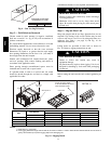
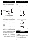
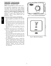
Mount the weatherproof cover to the backing plate as
shown in Fig. 27. Remove two slot fillers in the bottom of
the cover to permit service tool cords to exit the cover.
Check for full closing and latching.
RECEPTACLE
NOT SHOWN
COVER – WHILE-IN-USE
WEATHERPROOF
BASE PLATE FOR
GFCI RECEPTACLE
C09022
Fig. 27 -- Weatherproof Cover Installation
Non--unit powered type: This type requires the field
installation of a general--purpose 125--volt 15--A circuit
powered from a source elsewhere in the building. Observe
national and local codes when selecting wire size, fuse or
breaker requirements and disconnect switch size and
location. Route 125--v power supply conductors into the
bottom of the utility box containing the duplex receptacle.
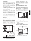
Unit--powered type: A unit--mounted transformer is
factory--installed to stepdown the main power supply
voltage to the unit to 115--v at the duplex receptacle. This
option also includes a manual switch with fuse, located in
a control box and mounted on a bracket behind the
convenience outlet; access is through the unit’s control
box access panel. See Fig. 26.
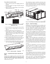
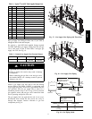
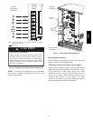
The primary leads to the convenience outlet transformer
are not factory--connected. If local codes permit, the
transformer primary leads can be connected at the
line--side terminals on the unit--mounted non--fused
disconnect switch; this will provide service power to the
unit when the unit disconnect switch is open. See Fig. 28.
C10730
UNIT
VOLTAGE
CONNECT
AS
PRIMARY
CONNECTIONS
TRANSFORMER
TERMINALS
208,
230
240
L1: RED +YEL
L2: BLU + GRA
H1 + H3
H2 + H4
460 480
L1: RED
Splice BLU + YEL
L2: GRA
H1
H2 + H3
H4
575 600
L1: RED
L2: GRA
H1
H2
Fig. 28 -- Powered Convenience Outlet Wiring
48HC