


17
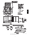
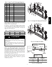
Table 2 – Typical
3
/
4
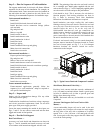
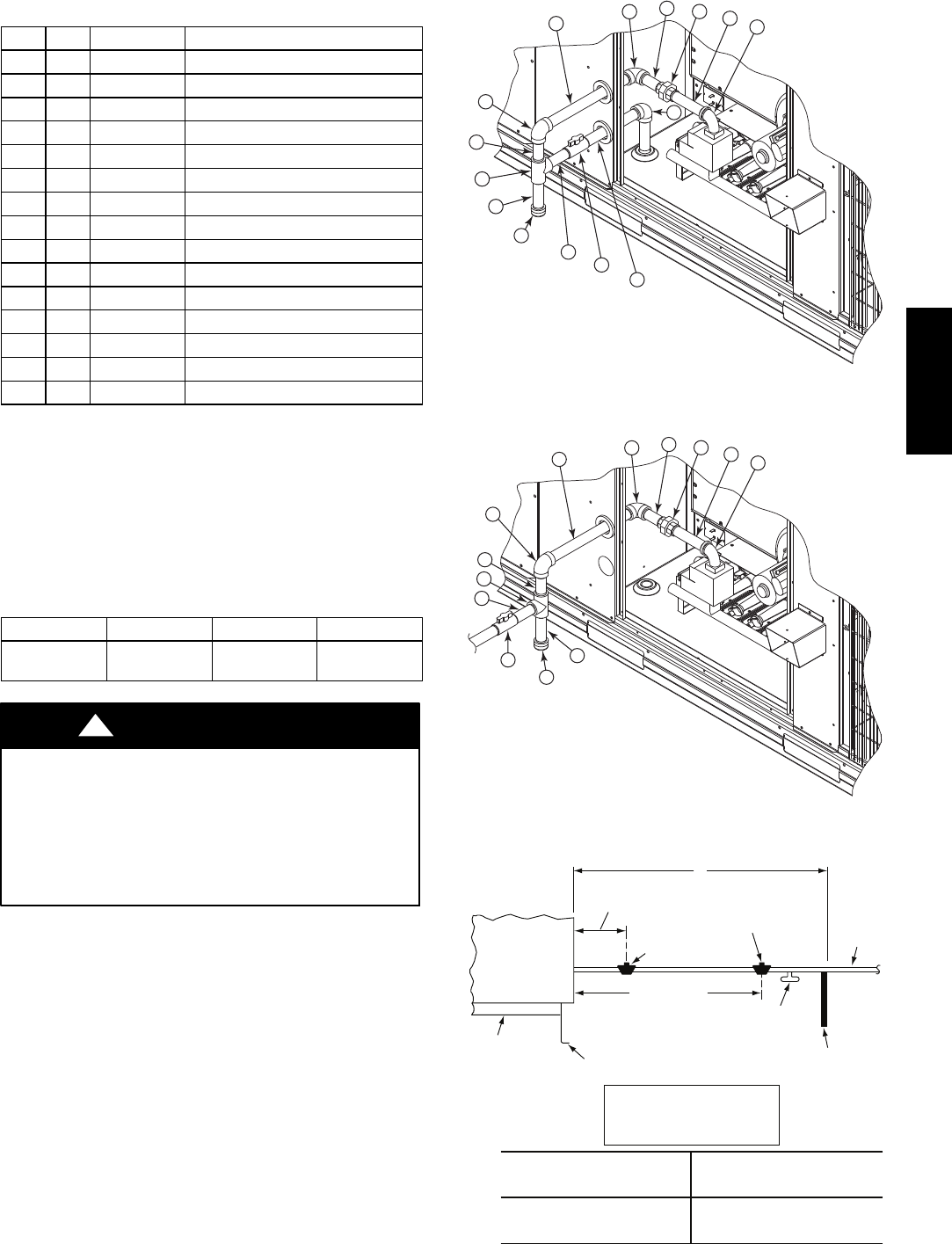
--in NPT Field Supplied Piping Parts
Item Qty CPN Description
1 1 CA15RA201 90 Deg Street Elbow
2 1 CA01CA226 5 Inch Long Nipple
3 1 CA85RA201 Ground---Joint Union
4 1 CA01CA218 3 Inch Long Nipple
5 1 CA05RA201 90 Deg Elbow
6 1 CA01CA250 12 Inch Long Nipple
7 1 CA05RA201 90 Deg Elbow
8 1 CA01CA218 3 Inch Long Nipple
9 1 CA20RA201 TEE
10 1 CA01CN222 4 Inch Long Nipple (Sediment Trap)
11 1 CA38RA201 Cap
12 1 CA01CA220 3
1
/
2
Inch Long Nipple
13 1 GB30 NIBCO
R
Ball V alve
14 1 CA01CA238 8 Inch Long Nipple
15 1 CA05RA201 90 Deg Elbow
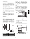
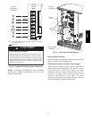
Pipe gas supply into 90 degree elbow item 15 (see Table 2)
through the hole in the unit basepan.
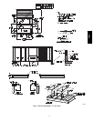
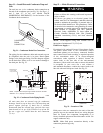
For typical
3
/
4
inch NPT field supplied fittings required
for NON Thru--Base gas supply starting from the unit gas
valve, omit items 14 and 15 from Table 2 and pipe gas
supply into TEE. See Fig. 18.
Table 3 – Natural Gas Supply Line Pressure Ranges
UNIT MODEL UNIT SIZE MIN MAX
48HC** 17, 20, 24, 28
5.0 in. wg
(1246 Pa)
13.0 in. wg
(3240 Pa)
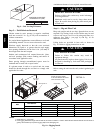
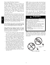
EQUIPMENT DAMAGE HAZARD
Failure to follow this caution may result in damage
to equipment.
When connecting the gas line to the unit gas valve,
the installer MUST use a backup wrench to prevent
damage to the valve.
CAUTION
!
Install a gas supply line that runs to the unit heating
section. Refer to the NFPA 54/NFGC or equivalent code
for gas pipe sizing data. Do not use a pipe smaller than the
size specified. Size the gas supply line to allow for a
maximum pressure drop of 0.5--in wg (124 Pa) between
gas regulator source and unit gas valve connection when
unit is operating at high--fire flow rate.
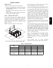
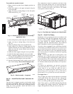
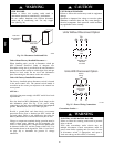
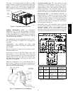
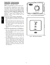
The gas supply line can approach the unit in two ways:
horizontally from outside the unit (across the roof), or
through unit basepan. Observe clearance to gas line
components per Fig. 19.
15
14
13
12
11
10
9
8
7
6
5
4
3
2
1
C10999
Fig. 17 -- Gas Supply Line Piping with Thru--Base
13
12
11
10
9
8
7
6
5
4
3
2
1
C101006
Fig. 18 -- Gas Supply Line Piping
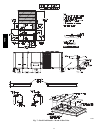
LEGEND
*
Field supplied.
NOTE: Follow all local codes.
NFGC – National Fuel Gas Code
STEEL PIPE
NOMINAL DIAMETER
(in.)
SPACINGOFSUPPORTS
X DIMENSION
(ft)
1
/
2
3
/
4
or 1
1
1
/
4
or larger
6
8
10
X
BASE UNIT
BASE RAIL
ROOF
CURB
9” MINIMUM CLEARANCE
FOR PANEL REMOVAL
MANUAL GAS
SHUTOFF VALVE
*
GAS
REGULATOR
*
48” MINIMUM
DRIP LEG
PER NFGC
*
FIELD-
FABRICATED
SUPPORT
*
FROM
GAS
METE
R
C11121
Fig. 19 -- Gas Piping Guide
48HC