


20
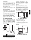
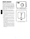
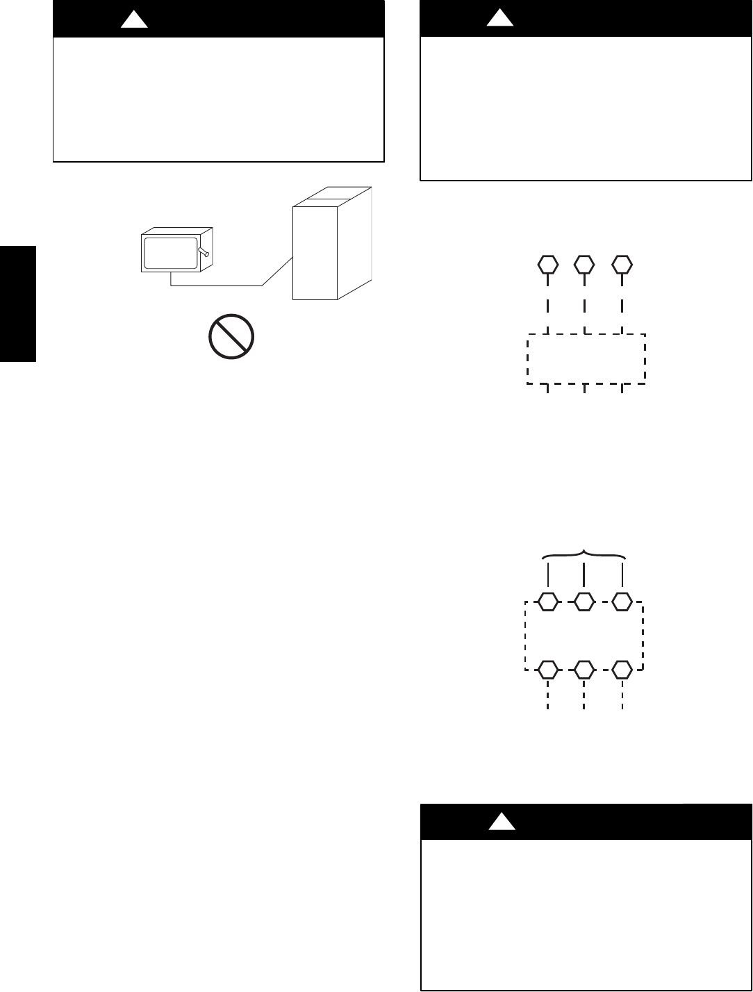
FIRE HAZARD
Failure to follow this warning could result in
intermittent operation or unsatisfactory performance.
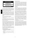
Do not connect aluminum wire between disconnect
switch and air conditioning unit. Use only copper
wire.(SeeFig.24.)
!
WARNING
COPPER
WIRE ONLY
ELECTRIC
DISCONNECT
SWITCH
ALUMINUM
WIRE
A93033
Fig. 24 -- Disconnect Switch and Unit
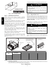
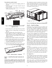
Units without Factory--Installed Disconnect —
When installing units, provide a disconnect switch per
NEC (National Electrical Code) of adequate size.
Disconnect sizing data is provided on the unit informative
plate. Locate on unit cabinet or within sight of the unit per
national or local codes. Do not cover unit informative
plate if mounting the disconnect on the unit cabinet.
Units with Factory--Installed Disconnect —
The factory--installed option disconnect switch is located
in the main control box. The manual switch handle is
accessible on the corner post adjacent to the control box
access panel.
All Units --
All field wiring must comply with NEC and all local code
requirements.
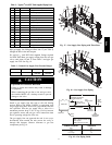
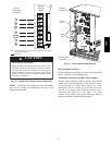
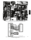
Size wire based on MCA (Minimum Circuit Amps) on the
unit informative plate. See Fig. 25 for power wiring
connections to the unit power terminal block and equipment
ground. Maximum wire size is 2/0 AWG per pole.
Provide a ground--fault and short--circuit over--current
protection device (fuse or breaker) per NEC Article 440
(or local codes). Refer to unit informative data plate for
MOCP (Maximum Over--current Protection) device size.
Voltage to compressor terminals during operation must be
within voltage range indicated on unit nameplate. See
Table 11. On 3--phase units, voltages between phases must
be balanced within 2% and the current within 10%. Use
the formula shown in the legend for Table 11 (see Note 2
on page 49) to determine the percent of voltage
imbalance.
UNIT DAMAGE HAZARD
Failure to follow this caution may result in equipment
damage.
Operation on improper line voltage or excessive phase
imbalance constitutes abuse and may cause damage to
electrical components. Such operation would invalidate
any applicable Carrier warranty.
CAUTION
!
11 12 13
L1
L2 L3
TB1
208/230-3-60
460-3-60
575-3-60
Units Without Disconnect Option
Units With Disconnect Option
T1 T2 T3
L1 L2 L3
L1 L2 L3
Factory
Wiring
Disconnect
per
NEC
Optional
Disconnect
Switch
C101000
Fig. 25 -- Power Wiring Connections
Convenience Outlets —
ELECTRICAL OPERATION HAZARD
Failure to follow this warning could result in personal
injury or death.
Units with convenience outlet circuits may use
multiple disconnects. Check convenience outlet for
power status before opening unit for service. Locate
its disconnect switch, if appropriate, and open it.
Lock--out and tag--out this switch, if necessary.
!
WARNING
48HC