


16
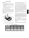
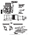
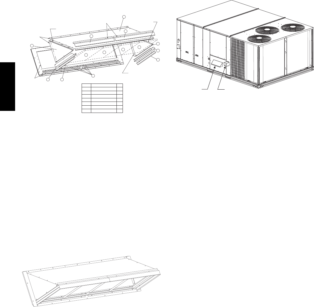
To assemble the outside air hood:
1. Remove hood top panel from shipping position on
unit end.
2. Install four angles to the upper end panel using the
screws provided.
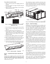
3. Apply seal strip to mating flanges on the side plates
of the hood (see Fig. 14).
A
pply Seal Strips
to the back of
these flanges
Apply Seal Strip
to the front of
this flange
Apply Seal Strip
to the front of
this flange
Apply Seal Strip
to the back of
this flange
Seal Strips
Apply Seal Strips
to the back of
these surfaces
7
7
2
2
1
3
4
4
4
4
5
6
5
6
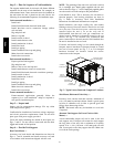
Item # Description Qty
1 Angles 4
2 Side Plates 2
3 Hood 1
4 Outdoor Air Screens 4
5 Side Filter Supports 2
6 Side Drip Angles 2
7 Top Diverters 2
C09079
Fig. 14 -- Hood Part Identification and Seal Strip
Application Areas
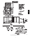
4. Secure side plates to panel using the screws provided.
5. Apply seal strip to mating flange of the hood (see
Fig. 14).
6. Secure top flange using screws provided in kit.
7. Install outdoor air screens by sliding them into the
channel formed by the four angles installed in step 2.
Make sure that the screens extend across the entire
length of the hood.
8. Install side filter supports using the screws provided.
9. Install side drip angles using the screws provided.
10. Run a continuous length of seal strip across the hood
covering the engagement holes in the lower hood.
11. Install top diverter using the screws provided.
12. On units with barometric relief, remove screws at bot-
tom of relief damper. Do not discard damper door.
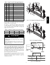
C09090
Fig. 15 -- Hood Assembly – Completed
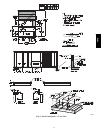
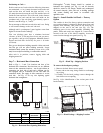
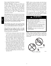
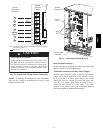
Step 9 — Install Flue Hood and Combustion Air
Hood
The flue hood is shipped screwed to the fan deck inside
the burner compartment. Remove the burner access panel
and then remove the flue hood from its shipping location.
Using the screws provided, install flue hood in the
location shown in Fig. 16.
The combustion air hood is attached to the back of the
burner access panel. Remove the two screws securing the
hood to the back of the burner access panel. Using the two
screws, re--attach the hood to the front of the burner
access panel as shown in Fig. 16.
Flue Hood
Combustion
Air Hood
C10744
Fig. 16 -- Flue Hood and Combustion Air Hood Details
Step 10 — Install Gas Piping
Installation of the gas piping must be in accordance with
local building codes and with applicable national codes.
In U.S.A., refer to NFPA 54/ANSI Z223.1 National Fuel
Gas Code (NFGC). In Canada, installation must be
accordance with the CAN/CSA B149.1 and CAN/CSA
B149.2 installation codes for gas burning appliances.
This unit is factory equipped for use with Natural Gas fuel
at elevations up to 2000 ft (610 m) above sea level. Unit
may be field converted for operation at elevations above
2000 ft (610 m) and/or for use with liquefied petroleum
fuel. See accessory kit installation instructions regarding
these accessories.
NOTE: Furnace gas input rate on rating plate is for
installation up to 2000 ft (610 m) above sea level. In
U.S.A. the input rating for altitudes above 2000 ft (610 m)
must be derated by 4% for each 1000 ft (305 m) above sea
level. In Canada the input rating must be derated by 10%
for altitudes of 2000 ft (610 m) to 4500 ft (1372 m) above
sea level.
For natural gas applications, gas pressure at unit gas
connection must not be less than 5 in. wg (1246 Pa) or
greater than 13 in. wg (3240 Pa) while the unit is
operating. For liquified petroleum applications, the gas
pressure must not be less than 11 in. wg (2740 Pa) or
greater than 13 in. wg (3240 Pa) at the unit connection.
Gas Supply Line —
The gas supply pipe enters the unit adjacent to the burner
access panel on the front side of the unit, through the
grommeted hole. The gas connection to the unit is made
to the
3
/
4
in. FPT gas inlet port on the unit gas valve.
Table 2 lists typical
3
/
4
inch NPT (National Pipe Thread)
field supplied pipe fittings required for Thru--Base gas
supply, starting from the unit gas valve (see Fig. 17).
48HC