


22
2.0
50HE501288
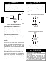
NOTICE/AVIS
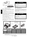
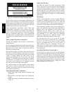
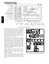
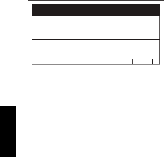
Convenience Outlet Utilization
Maximum Intermittent Use 15 - Amps
Maximum Continuous Use 8 - Amps
Observe a 50% limit on the circuit
Loading above 8 - Amps
Utilisation de la prise utilitaire
Usage intermittent maximum 15 - Amps
Usage continu maximum 8 - Amps
Observez une limite de 50% sur le circuit
Chargement au-dessus de 8 - Amps
C10077
Fig. 29 -- Convenience Outlet Utilization Notice
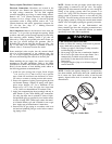
Test the GFCI receptacle by pressing the TEST button on
the face of the receptacle to trip and open the receptacle.
Check for proper grounding wires and power line phasing
if the GFCI receptacle does not trip as required. Press the
RESET button to clear the tripped condition.
Using unit--mounted convenience outlets: Units with
unit--mounded convenience outlet circuits will often
require that two disconnects be opened to de--energize all
power to the unit. Treat all units as electrically energized
until the convenience outlet power is also checked and
de--energization is confirmed. Observe National Electrical
Code Article 210, Branch Circuits, for use of convenience
outlets.
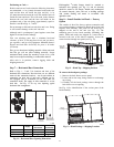
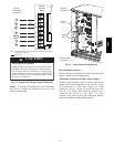
Factory--Option Thru--Base Connections —
All units are equipped with the ability to bring utilities
through the base.
Gas is brought up through an embossed area located in the
gas section behind the gas entrance post. Access is gained
through the gas access panel. A knock out must be
removed to accomplish this.
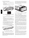
The electrical entrance is located in the control box area
and can be accessed through the control box access panel.
An embossed area is provided with three knock outs. High
voltage is brought through the multi knock out by
removing the appropriate size for the size of the fitting
required. A
7
/
8
--in. knock out is provided for low voltage.
An additional
7
/
8
--in. knock out is provided for a 115 volt
line which is used when the unit is equipped with the
non--unit powered convenience outlet option.
All required fittings are field supplied. Install fittings
when access to both top and bottom of the base pan is
available. See electrical and gas connections for routing
and connection information.
Units without Thru--Base Connections —
1. Install liquid tight conduit between disconnect and
control box.
2. Pull correctly rated high voltage wires through the
conduit.
3. Install power lines to terminal connections as shown
in Fig. 25.
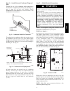
Field Control Wiring —
The 48HC unit requires an external temperature control
device. This device can be a thermostat (field--supplied)
or a PremierLink controller (available as factory--installed
option or as field--installed accessory, for use on a Carrier
Comfort Network or as a stand alone control) or the RTU
Open for Building Management Systems using non--CCN
protocols (RTU Open is available as a factory--installed
option only).
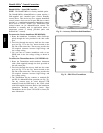
Thermostat —
Install a Carrier--approved accessory 2--stage thermostat
according to installation instructions included with the
accessory. Locate the thermostat accessory on a solid wall
in the conditioned space to sense average temperature in
accordance with the thermostat installation instructions.
If the thermostat contains a logic circuit requiring 24--v
power, use a thermostat cable or equivalent single leads of
different colors with minimum of seven leads. If the
thermostat does not require a 24--v source (no “C”
connection required), use a thermostat cable or equivalent
with minimum of six leads. Check the thermostat
installation instructions for additional features which
might require additional conductors in the cable.
For wire runs up to 50 ft. (15 m), use no. 18 AWG
(American Wire Gage) insulated wire (35_C minimum).
For50to75ft.(15to23m),useno.16AWGinsulated
wire (35_C minimum). For over 75 ft. (23 m), use no. 14
AWG insulated wire (35_ C minimum). All wire sizes
larger than no. 18 AWG cannot be directly connected to
the thermostat and will require a junction box and splice
at the thermostat.
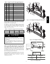
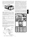
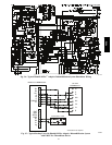
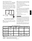
Unit without Thru--Base Connection Kit —
Correctly rated low voltage wire can be routed through the
rubber grommet located on the corner post adjacent to the
control box access panel. Route wire through the grommet
and then route the wire behind the corner post utilizing the
factory provided wire ties secured to the control box. This
will insure separation of the field low voltage wire and the
high voltage circuit. Route the low voltage wire to the
central terminal board. See Fig. 30.
48HC