


39
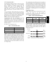
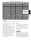
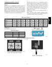
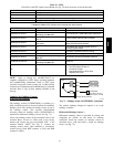
Table 9 – RTU Open Controller Inputs and Outputs
POINT NAME
BACnet OBJECT
NAME
TYPE OF I/O
CONNECTION PIN
NUMBER(S)
DEDICATED INPUTS
Space Temp / Zone Temp zone_temp AI (10K Thermist or) J20 --- 1, 2
Supply Air Temperature sa_temp AI (10K Thermistor) J2 --- 1, 2
Outdoor Air Temperature oa_temp AI (10K Thermistor) J2 --- 3, 4
Space Temperature Offset Pot stpt_adj_offset AI (100K Potentiometer) J20 --- 3
Safety Chain Feedback safety_status DI (24 VAC) J1 --- 9
Compressor Safety Status comp_status DI (24 VAC) J1 --- 2
Fire Shutdown Status firedown_status DI (24 V AC) J1 --- 10
Enthalpy Status enthalpy_status DI (24 VAC) J2 --- 6
Humidistat Input Status humstat_status DI (24 VAC) J5 --- 7
CONFIGURABLE INPUTS
Indoor Air CO2 iaq AI (4 --- 20 ma)
J4 --- 2 or J4 --- 5Outdoor Air CO2 oaq AI (4--- 20 ma)
Space Relative Humidity space_rh AI (4 --- 20 ma)
Supply Fan Status* sfan_status DI (24 VAC)
J5 --- 1 or J5 --- 3 or
J55orJ5---7
Filter Status* filter_status DI (24 VAC)
Door Contact Input* door_contact_status DI (24 VAC)
Occupancy Contact* occ_contact_status DI (24 VAC)
OUTPUTS
Economizer Output econ_output AO (4 --- 20ma) J2 --- 5
SupplyFanRelayState sfan DO Relay (24VAC , 1A) J1--- 4
Compressor 1 Relay State comp_1 DO Relay (24VAC , 1A) J1--- 8
Compressor 2 Relay State comp_2 DO Relay (24VAC , 1A) J1--- 7
Heat Stage 1 Relay State heat_1 DO Relay (24VAC , 1A) J1 --- 6
Heat Stage 2 Relay State heat_2 DO Relay (24VAC , 1A) J1 --- 5
Power Exhaust Relay State pexh DO Relay (24VAC , 1 A) J11 --- 3
Dehumidification Relay State dehum DO Relay (24VAC, 1A) J11 --- 7, 8
LEGEND
AI --- Analog Input
AO --- Analog Output
DI --- Discrete Input
DO --- Discrete Output
* These inputs (if installed) take the place of the default input on the specific channel according to schematic.
Parallel pins J5---1 = J2---6, J5 ---3 = J1---10, J5---5 = J1---2 are used for field---installation.
The RTU Open controller requires the use of a Carrier
space sensor. A standard thermostat cannot be used with
the RTU Open system.
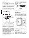
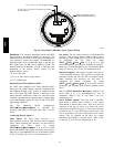
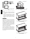
Supply Air Temperature (SAT) Sensor —
On FIOP--equipped 48HC unit, the unit is supplied with a
supply--air temperature (SAT) sensor (33ZCSENSAT). This
sensor is a tubular probe type, approx 6--inches (12.7 mm) in
length. It is a nominal 10--k ohm thermistor.
The SAT is factory--wired. The SAT probe is wire--tied to the
supply--air opening (on the horizontal opening end) in its
shipping position. Remove the sensor for installation.
Re--position the sensor in the flange of the supply--air
opening or in the supply air duct (as required by local
codes). Drill or punch a
1
/
2
--in. hole in the flange or duct.
Use two field--supplied, self--drilling screws to secure the
sensor probe in a horizontal orientation. See Fig. 40.
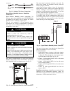
Outdoor Air Temperature (OAT) Sensor —
The OAT is factory--mounted in the EconoMi$er2 (FIOP or
accessory). It is a nominal 10k ohm thermistor attached to
an eyelet mounting ring.
EconoMi$er2 —
The RTU Open control is used with EconoMi$er2 (option
or accessory) for outdoor air management. The damper
position is controlled directly by the RTU Open control;
EconoMi$er2 has no internal logic device.
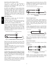
Outdoor air management functions can be enhanced with
field--installation of these accessory control devices:
Enthalpy control (outdoor air or differential sensors)
Space CO
2
sensor
Outdoor air CO
2
sensor
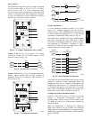
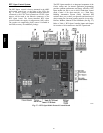
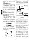
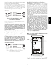
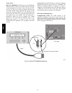
Field Connections
Field connections for accessory sensors and input devices
are made the RTU Open, at plugs J1, J2, J4, J5, J11 and
J20. All field control wiring that connects to the RTU
Open must be routed through the raceway built into the
corner post as shown in Fig. 31. The raceway provides the
UL required clearance between high-- and low--voltage
wiring. Pass the control wires through the hole provided in
the corner post, then feed the wires thorough the raceway
48HC