


29
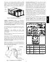
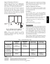
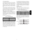
Supply Air Temperature (SAT) Sensor —
On FIOP--equipped 48HC unit, the unit is supplied with a
supply--air temperature (SAT) sensor (33ZCSENSAT).
This sensor is a tubular probe type, approx 6--inches (12.7
mm) in length. It is a nominal 10--k ohm thermistor.
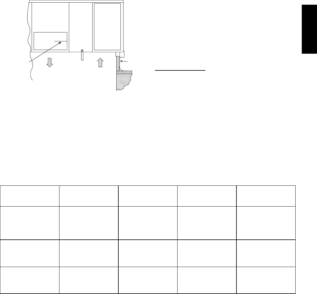
The SAT is factory--wired. The SAT probe is mounted in
the fan deck (see Fig. 40). It can be removed or
remounted per local codes.. Drill or punch a 1/2--in. hole
in the flange or duct. Use two field--supplied, self--drilling
screws to secure the sensor probe in a horizontal
orientation. Insure that the sensor wires do not contact the
hot surface of the heat exchanger.
SUPPLY AIR
RETURN AIR
SUPPLY AIR
TEMPERATURE
SENSOR
ROOF
CURB
C10733
Fig. 40 -- Mounting Location for Supply Air
Temperature (SAT) Sensor on 48HC Units
NOTE: Refer to Form 33CS--67SI for complete
PremierLink configuration, operating sequences and
troubleshooting information. Have a copy of this manual
available at unit start--up.
NOTE: The sensor must be mounted in the discharge
airstream downstream of the cooling coil and any heating
devices. Be sure the probe tip does not come in contact
with any of the unit’s heater surfaces.
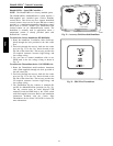
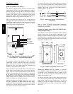
Outdoor Air Temperature (OAT) Sensor —
The OAT is factory--mounted in the EconoMi$er2 (FIOP
or accessory). It is a nominal 10k ohm thermistor attached
to an eyelet mounting ring.
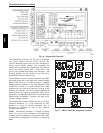
EconoMi$er2 —
The PremierLink control is used with EconoMi$er2
(option or accessory) for outdoor air management. The
damper position is controlled directly by the PremierLink
control; EconoMi$er2 has no internal logic device.
Outdoor air management functions can be enhanced with
field--installation of these accessory control devices:
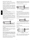
Enthalpy control (outdoor air or differential sensors)
Space CO
2
sensor
Outdoor air CO
2
sensor
Refer to Table 4 for accessory part numbers.
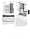
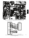
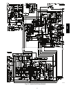
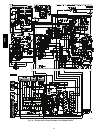
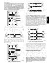
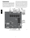
Field Connections
Field connections for accessory sensor and input devices
are made at the 16--pole terminal block (TB3, see Fig. 38
and Fig. 39) located on the control box top shelf in front
of the PremierLink control. Some input devices also
require a 24--vac signal source; connect at CTB terminal
R at “THERMOSTAT” connection strip for this signal
source. See connections figures on following pages for
field connection locations (and for continued connections
at the PremierLink board inputs).
Table 5 provides a summary of field connections for units
equipped with Space Sensor. Table 6 provides a summary of
field connections for units equipped with Space Thermostat.
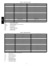
Table 4 – PremierLink Sensor Usage
APPLICATION
OUTDOOR AIR
TEMPERATURE
SENSOR
RETURN AIR
TEMPERATURE
SENSOR
OUTDOOR AIR
ENTHALPY SENSOR
RETURN AIR
ENTHALPY SENSOR
Differential Dry Bulb
Temperature with
PremierLink
(PremierLink requires
4 --- 20 mA Actuator)
Included ---
CRTEMPSN001A00
Required ---
33ZCT55SPT
or equivalent
--- ---
Single Enthalpy with
PremierLink
(PremierLink requires
4 --- 20mA Actuator)
Included ---
Not Used
---
Requires ---
33CSENTHSW
---
Differential Enthalpy
with PremierLink
(PremierLink requires
4 --- 20mA Actuator)
Included ---
Not Used
---
Requires ---
33CSENTHSW
or equivalent
Requires ---
33CSENTSEN
or equivalent
NOTES:
CO
2
Sensors (Optional):
33ZCSENCO2 --- Room sensor (adjustable). Aspirator box is required for duct mounting of the sensor.
33ZCASPCO2 --- Aspirator box used for duct---mounted CO
2
room sensor.
33ZCT55CO2 --- Space temperature and CO
2
room sensor with override.
33ZCT56CO2 --- Space temperature and CO
2
room sensor with override and setpoint.
48HC