


9
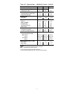
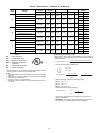
Table 5 — Refrigerant Specialties Part Numbers.
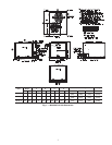
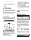
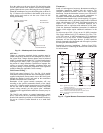
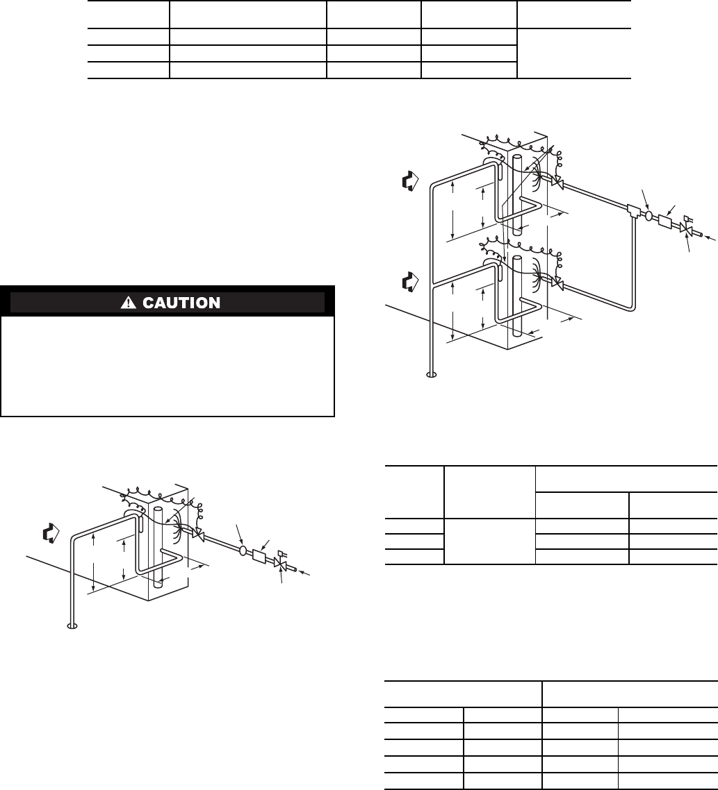
INSTALL LIQUID LINE SOLENOID VALVE —
It is recommended that a bi-directional solenoid valve be
placed in the main liquid line (see Figs. 5 & 6) between the
outdoor unit and the indoor coil. Locate the solenoid valve at
the end of the liquid line, near the outdoor unit connections,
with flow direction arrow pointed at the outdoor unit. Refer to
Table 5. (A liquid line solenoid valve is required when the
liquid line length exceeds 75 ft [23 m].) This valve prevents
refrigerant migration (which causes oil dilution) to the
compressor during the off cycle, at low outdoor ambient
temperatures. Wire the solenoid according to the unit label
diagram.
CAPACITY CONTROL LIQUID LINE SOLENOID VALVE
Evaporator capacity control via liquid solenoid valve is not rec-
ommended for use with 38AUQ models.
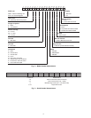
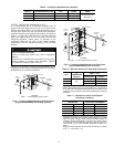
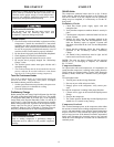
Fig.5 — Location of Sight Glass(es) and Filter Driers
(typical 38AUQ/40RUQ size 07 & 08 systems)
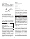
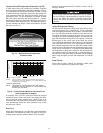
Fig.6 — Location of Sight Glass(es) and Filter Driers
(typical 38AUQ/40RUQ size 12 system)
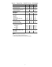
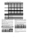
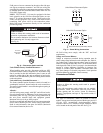
Table 6 — Minimum Outdoor Air Operating Temperature
*Applies to Cooling mode of operation only.
†Wind baffles (field-supplied and field-installed) are recommended
for all units with low ambient head pressure control. Refer to Low
Ambient Control Installation Instructions (shipped with accessory)
for details.
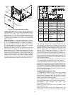
Table 7 — Insulation for Vapor Line Exposed
to Outdoor Conditions
*Recommended vapor line insulation for piping exposed to outdoor
conditions to prevent loss of heating during heating cycle. When
vapor line goes through interior spaces, insulation should be
selected to prevent condensation on cooling cycle. Heating capac-
ity should be reduced 1000 Btuh (295 W) if over 35 ft (11 m) of
vapor line with
3
/
4
in. (19 mm) insulation is exposed to outdoor con-
ditions.
†Closed cell foam insulation with a thermal conductivity of: 0.28 Btu
• in./ft
2
• h • °F (0.04 W/m • °C).
LIQUID LINE
SIZE (in.)
LIQUID LINE
SOLENOID VALVE (LLSV)
LLSV
COIL
SIGHT
GLASS
FILTER
DRIER
3
/
8
ALC-066208 AMG-24/50-60 HMI-1TT3
Provided with unit
See Table 4
1
/
2
ALC-066209
†
AMG-24/50-60 HMI-1TT4
5
/
8
ALC-066212 AMG-24/50-60 HMI-1TT5
†
38AUD units require TWO sets of parts.
UNIT DAMAGE HAZARD
Failure to follow this caution may result in equipment
damage.
Failure to use a solenoid valve relay (SUR) accessory may
cause overload of Comfort Alert Diagnostic Module
(CADM) and compressor alarm lock out.
15 DIAMS
MIN
10
DIAMS
8 DIAMS
MIN
INDOOR
COIL CKT
AIRFLOW
TXV
SENSING
BULB
EQUALIZER LINE
SIGHT GLASS
A LOCATION
TXV
FILTER DRIER
A LOCATION
LIQUID
LINE
SOLENOID
VALVE
FLOW
LEGEND
TXV — Thermostatic Expansion Valve
UNIT
%
COMPRESSOR
CAPACITY
MINIMUM OUTDOOR
TEMP — F (C)*
Standard Unit
Head Pressure
Control†
38AUQ07
100
35 (1.7) –20 (–28.9)
38AUQ08 35 (1.7) –20 (–28.9)
38AUQ12 35 (1.7) –20 (–28.9)
LENGTH OF EXPOSED
VAPOR LINE*
INSULATION THICKNESS†
ft m in. mm
10 3
3
/
8
10
25 8
1
/
2
13
35 11
3
/
4
19
50 15
3
/
4
19
LEGEND
TXV — Thermostatic Expansion Valve
INDOOR
COIL CKT 2
AIRFLOW
INDOOR
COIL CKT 1
AIRFLOW
15 DIAMS
MIN
10
DIAMS
8 DIAMS
MIN
TXV
SENSING
BULB
EQUALIZER LINE
SIGHT GLASS
LOCATION
TXV
CKT 2
FILTER DRIER
LOCATION
LIQUID
LINE
SOLENOID
VALVE
FLOW
TXV
SENSING
BULB
TXV
CKT 1
8 DIAMS
MIN
15 DIAMS
MIN
10
DIAMS