


31
Clean coil as follows:
1. Turn off unit power, tag disconnect.
2. Remove top panel screws on outdoor coil end of unit.
3. Remove coil corner post. To hold top panel open, place
coil corner post between top panel and center post.
4. Remove screws securing coil to compressor plate and
compressor access panel.
5. Use a water hose or other suitable equipment to flush
down the coil to remove dirt and debris. Clean the outer
surfaces with a stiff brush in the normal manner.
6. Remove the coil corner post from between the top panel
and center post. Reinstall the coil corner post and replace
all screws.
Totaline Environmentally Sound Coil Cleaner
Application Equipment
•2-
1
/
2
gallon garden sprayer
• Water rinse with low velocity spray nozzle
Totaline Environmentally Sound Coil Cleaner
Application Instructions
1. Proper eye protection such as safety glasses is recom-
mended during mixing and application.
2. Remove all surface loaded fibers and dirt with a vacuum
cleaner as described above.
3. Thoroughly wet finned surfaces with clean water and a
low velocity garden hose, being careful not to bend fins.
4. Mix Totaline environmentally sound coil cleaner in a 2
1
/
2
gallon garden spryer according to the instructions includ-
ed with the cleaner. The optimum solution temperature is
100°F (38°C).
NOTE: Do NOT USE water in excess of 130°F (54°C), as
the enzymatic activity will be destroyed.
5. Thoroughly apply Totaline environmentally sound coil
cleaner solution to all coil surfaces including finned area,
tube sheets and coil headers.
6. Hold garden sprayer nozzle close to finned areas and ap-
ply cleaner with a vertical, up-and-down motion. Avoid
spraying in horizontal pattern to minimize potential for
fin damage.
7. Ensure cleaner thoroughly penetrates deep into finned ar-
eas.
8. Interior and exterior finned areas must be thoroughly
cleaned.
9. Finned surfaces should remain wet with cleaning solution
for 10 minutes.
10. Ensure surfaces are not allowed to dry before rinsing. Re-
apply cleaner as needed to ensure 10-minute saturation is
achieved.
11. Thoroughly rinse all surfaces with low velocity clean wa-
ter using downward rinsing motion of water spray nozzle.
Protect fins from damage from the spray nozzle.
Service Parts
Listings of service parts for all units are available from the Re-
placement Components Division’s Electronic Parts Informa-
tion Catalog (EPIC). EPIC is available at Totaline stores, dis-
tributor and service office parts departments and on-line at
HVACPartners.com.
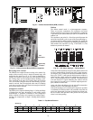
When entering EPIC, the full unit model number is required.
The model number includes the Design Revision reference val-
ue (see Fig. 2, Position 13). The unit model number is available
from the unit’s information data plate. (Do not use the “catalog
number” when using EPIC. The “catalog number” suppresses
the Design Revision value; failure to include Design Revision
value may cause an incorrect unit parts list to be displayed.)
When using EPIC, enter first four digits of the model number
only. Find appropriate model from sales packages listed. Be
sure to choose correct voltage and Design Revision.
EPIC is a product of RCD. To comment of the EPIC program,
use the “Comment” button inside the EPIC program.
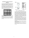
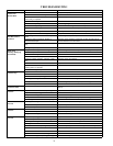
FASTENER TORQUE VALUES
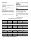
Table 16 — Torque Values
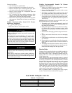
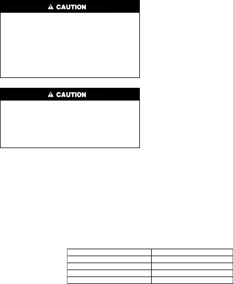
UNIT DAMAGE HAZARD
Failure to follow this caution may result in corrosion and
damage to the unit.
Harsh chemicals, household bleach or acid or basic clean-
ers should not be used to clean outdoor or indoor coils of
any kind. These cleaners can be very difficult to rinse out of
the coil and can accelerate corrosion at the fin/tube inter-
face where dissimilar materials are in contact. If there is dirt
below the surface of the coil, use the Totaline environmen-
tally sound coil cleaner as described above.
UNIT DAMAGE HAZARD
Failure to follow this caution may result in reduced unit
performance.
High velocity water from a pressure washer, garden hose,
or compressed air should never be used to clean a coil. The
force of the water or air jet will bend the fin edges and in-
crease airside pressure drop.
Compressor mounting bolts 65–75 in–lbs (734–847 N–cm)
Condenser fan motor mounting bolts 20 ±2 in–lbs (226 ±23 N–cm)
Condenser fan hub setscrew 84 ±2 in–lbs (949 ±136 N–cm)
High-flow service port 96 ±10 in–lbs (1085 ±23 N–cm)
Schrader-type service check valve 2–3 in–lbs (23–34 N–cm)