


7
.INSTALLATION
Jobsite Survey
Complete the following checks before installation.
1. Consult local building codes and the NEC (National
Electrical Code) ANSI/NFPA 70 for special installation
requirements.
2. Determine unit location (from project plans) or select unit
location.
3. Check for possible overhead obstructions which may in-
terfere with unit lifting or rigging.
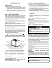
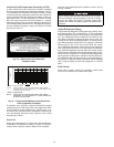
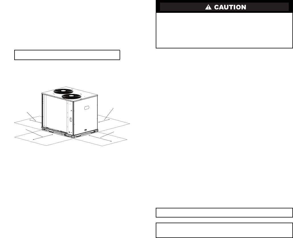
Step 1 — Plan for Unit Location
Select a location for the unit and its support system (pad, rails
or other) that provides for the minimum clearances required for
safety. This includes the clearance to combustible surfaces, unit
performance and service access below, around and above unit
as specified in unit drawings. See Fig. 4.
Select a unit mounting system that provides adequate height to
allow for removal and disposal of frost and ice that will form
during the heating-defrost mode.
NOTE: Consider also the effect of adjacent units on airflow
performance and control box safety clearance.
Do not install the outdoor unit in an area where fresh air supply
to the outdoor coil may be restricted or when recirculation from
the condenser fan discharge is possible. Do not locate the unit
in a well or next to high walls.
Evaluate the path and required line length for interconnecting
refrigeration piping, including suction riser requirements (out-
door unit above indoor unit), liquid line lift (outdoor unit below
indoor unit) and hot gas bypass line. Relocate sections to mini-
mize the length of interconnecting tubing.
Although unit is weatherproof, avoid locations that permit
water from higher level runoff and overhangs to fall onto the
unit.
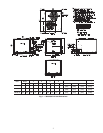
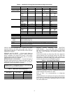
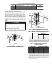
Fig. 4 — Service Clearance Dimensional Drawing
Step 2 — Complete Pre-Installation Checks
CHECK UNIT ELECTRICAL CHARACTERISTIC —
Confirm before installation of unit that voltage, amperage and
circuit protection requirements listed on unit data plate agree
with power supply provided.
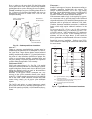
UNCRATE UNIT — Remove unit packaging except for the
top skid assembly, which should be left in place until after the
unit is rigged into its final location.
INSPECT SHIPMENT — File a claim with shipping com-
pany if the shipment is damaged or incomplete.
CONSIDER SYSTEM REQUIREMENTS
• Consult local building codes and National Electrical
Code (NEC, U.S.A.) for special installation requirements.
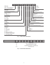
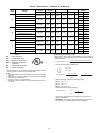
• Allow sufficient space for airflow clearance, wiring,
refrigerant piping, and servicing unit. See Fig.1 for unit
dimensions and weight distribution data.
• Locate the unit so that the outdoor coil (condenser) air-
flow is unrestricted on all sides and above.
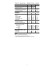
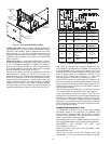
• The unit may be mounted on a level pad directly on the
base channels or mounted on raised pads at support
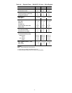
points. See Tables 1A and 1B for unit operating weights.
See Fig. 1 for weight distribution based on recommended
support points.
NOTE: If vibration isolators are required for a particular
installation, use the data in Fig. 1 to make the proper
selection.
Step 3 — Prepare Unit Mounting Support
Slab Mount
Provide a level concrete slab that extends a minimum of 6 in.
(150 mm) beyond unit cabinet. Install a gravel apron in front of
condenser coil air inlet to prevent grass and foliage from
obstructing airflow.
Step 4 — Rig and Mount the Unit
.
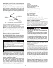
RIGGING — These units are designed for overhead rigging.
Refer to the rigging label for preferred rigging method. Spread-
er bars are not required if top crating is left on the unit. All pan-
els must be in place when rigging. As further protection for coil
faces, plywood sheets may be placed against the sides of the
unit, behind cables. Run cables to a central suspension point so
that the angle from the horizontal is not less than 45 degrees.
Raise and set the unit down carefully.
If it is necessary to roll the unit into position, mount the unit on
longitudinal rails, using a minimum of 3 rollers. Apply force to
the rails, not the unit. If the unit is to be skidded into position,
place it on a large pad and drag it by the pad. Do not apply any
force to the unit.
Raise from above to lift the unit from the rails or pad when unit
is in its final position.
After the unit is in position, remove all shipping materials and
top crating.
Step 5 — Complete Refrigerant Piping
Connections
Refrigerant lines must be carefully designed and constructed to
ensure equipment reliability and efficiency. Line length, pres-
sure drop, compressor oil return, and vertical separation are
several of the design criteria that must be evaluated. See
Table 2.
DO NOT BURY REFRIGERATION LINES.
REAR:
Min 18” (457 mm)
requried for service
Note: Observe requirements for 39” (914 mm) operating clearance
on either Left or Rear coil opening.
RIGHT:
Min 18” (457 mm)
requried for service
LEFT:
Min 18” (457 mm)
requried for service
FRONT:
42” (1067 mm)
UNIT DAMAGE HAZARD
Failure to follow this caution may result in equipment
damage.
All panels must be in place when rigging. Unit is not
designed for handling by fork truck.
IMPORTANT: Do not bury refrigerant piping underground.
IMPORTANT: A refrigerant receiver is not provided with
the unit. Do not install a receiver.