


28
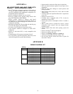
COMFORT ALERT DIAGNOSTIC
MODULE
The Comfort Alert Diagnostic Module (CADM) monitors and
analyzes data from the Copeland Scroll
®
three-phase compres-
sor and the thermostat demand. The CADM also provides a
3-minute anti-recycle time delay to compressor cycling.
The CADM detects causes for electrical and system related
failures. Flashing LEDs communicate the Alert codes to guide
service technicians in accurately and quickly troubleshooting
the system and determining root cause for the failure.
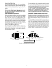
Inputs to the CADM include 24-vac power, demand signal Y,
compressor contactor coil (common side) and compressor
power leads (from the compressor contactor).
Control of the compressor contactor coil is through a contact
between terminals P and C.
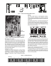
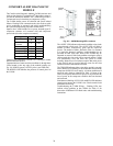
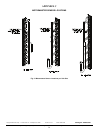
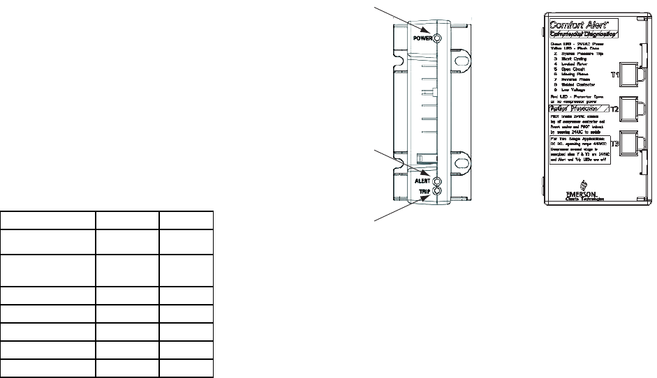
Communications of status and alert conditions is through three
LEDs located on the top edge of the module housing (see
Fig. 30): POWER (green), ALERT (yellow), and TRIP (red).
The POWER LED indicates the presence of control power to
the CADM.
Fig. 30 — CADM Housing/LED Locations
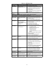
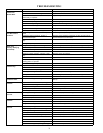
The ALERT LED indicates an abnormal condition exists in the
system through a flash code. The ALERT LED will blink a
number of times consecutively, pause and the repeat the
process. The number of blinks, defined in Table 14, correlates
to a particular abnormal condition; troubleshooting tips are
provided for each Alert code. Reset of the ALERT may be
automatic or manual. If the fault condition causing the Alert is
self-corrected, the Alert code will be removed and the CADM
will automatically reset and allow the system to restart
normally. Manual reset for lockouts requires that main power
to the 38AUQ unit be recycled after the cause for the Alert
condition has been detected and corrected.
The TRIP LED indicates either a time-delay period is currently
active (RED LED is blinking) or the module has locked out the
compressor (RED LED is on steady). A lockout condition will
occur for some faults as identified in Table 14. Reset of the
TRIP LED requires that unit main power be recycled after the
loss of power to the compressor condition has been detected
and corrected.
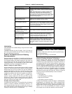
Simultaneous Blinking of YELLOW and RED LEDs indicates
control power input to the CADM is low. Check control circuit
transformer and wiring.
Troubleshooting the CADM Wiring – Flashing LEDs also
indicate wiring problems to the CADM. See Table 15 for
discussion of additional LED flash codes and troubleshooting
instructions.
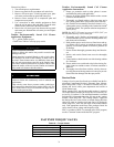
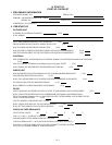
Input Terminal Voltage
Control Power
R 24-V
Control
Common
C 24-V
Demand Y 24-V
Contactor Coil P 24-V
Compressor T1 T1 Line
Compressor T2 T2 Line
Compressor T3 T3 Line
POWER
(GRN)
ALERT
(YEL)
TRIP
(RED)