


22
Heat Pump Controls
Compressor Protection
Compressor Overcurrent
The compressor has internal limbered motor protection.
Compressor Overtemperature
The compressor has an internal protector to protect it against
excessively high discharge gas temperatures.
High Pressure Switch
The system is provided with a high pressure switch mount-
ed on the discharge line. The switch is stem-mounted and
brazed into the discharge tube. Trip setting is 630 ± 10 psig
(4344 ± 69 kPa) when hot. Reset is automatic at 505 ± 20
psig (3482 ± 140 kPa).
Loss of Charge Switch
The system is protected against a loss of charge and low
evaporator coil loading condition by a loss of charge switch
located on the liquid line and a freeze protection thermostat on
the indoor coil. The switch is stem-mounted. Loss of Charge
Switch trip setting is 27 psig ± 3 psig (186 ±21 kPa). Reset is
automatic at 44 ±5 psig (303 ± 35 kPa).
Outdoor Fan Motor Protection
The outdoor fan motor is internally protected against overtem-
perature.
Control Circuit, 24-V
The control circuit is protected against overcurrent conditions
by a circuit breaker mounted on control transformer TRAN.
Reset is manual.
Crankcase Heater
The heater prevents refrigerant migration and compressor oil
dilution during shutdown whenever compressor is not operat-
ing. The heater is wired to cycle with the compressor; the heat-
er is off when compressor is running, and on when compressor
is off.
The crankcase heater will operate as long as the power circuit
is energized.
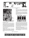
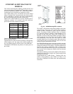
Commercial Defrost Control
The Commercial Defrost Control Board (DFB) coordinates
thermostat demands for supply fan control, 1 or 2 stage
cooling, 1 or 2 stage heating, emergency heating and defrost
control with unit operating sequences. See Fig. 22 for board
arrangement.
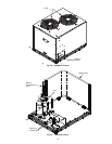
The DFB is located in the 38AUQ's main control box (see
Fig. 21). All connections are factory-wired. Refer to Table 12
for details of DFB Inputs and Outputs.
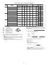
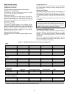
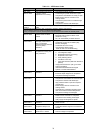
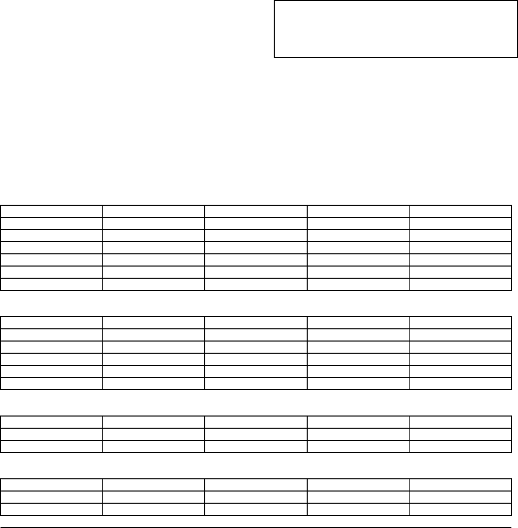
Table 12 —38AUQ Defrost Board I/O and Jumper Configurations
IMPORTANT: Never open any switch or disconnect that
energizes the crankcase heater unless unit is being serviced
or is to be shut down for a prolonged period. After a pro-
longed shutdown on a service job, energize the crankcase
heater for 24 hours before starting the compressor.
Inputs
Point Name Type of I/O Connection Pin Number Unit Connection Note
G Fan DI, 24-vac P2-3 Not used
Y1 Cool 1 DI, 24-vac P2-5 TB-Y1
Wi Heat 1 DI, 24-vac P2-7 TB-W1
R Power 24-vac P3-1 TRAN2
C Common 24-vac, ground P3-3 TRAN2
DFT1 Defrost Switch DI, 24-vac DFT-1 to DFT-1 DFB
Outputs
Point Name Type of I/O Connection Pin Number Unit Connection Note
OF OD Fan DO, 24-vac OF OFR
RVS1 DO, 24-vac P3-7 to P3-5 RVS1 Energize in COOL
RVS2 DO, 24-vac P3-6 to P3-4 RVS2 Energize in COOL
COMP 1 DO, 24-vac P3-10 CADM1-Y
HEAT 2 DO, 24-vac E-HEAT HC-1 (TB4-1)
Configuration
Point Name Type of I/O Connection Pin Number Unit Connection Note
Select Jumper 24-vac P1-1
1 Compressor 24-vac P1-2
Speed-Up Configuration
Point Name Type of I/O Connection Pin Number Unit Connection Note
Speed-Up Jumper JMP17
Speed-Up Jumper JMP18
Jumper for 1-3 secs: Factory Test, defrost runs for 12 seconds or less
Jumper for 5-20 secs: Forced Defrost, defrost runs for 30 secs if DFT2 is open