


11
Field power wires are connected to the unit at line-side pres-
sure lugs on compressor contactor C and TB1 (see wiring dia-
gram label for control box component arrangement) or at facto-
ry-installed option non-fused disconnect switch. Max wire size
is #4 AWG (copper only).
NOTE: TEST LEADS - Unit may be equipped with short
leads (pigtails) on the field line connection points on con-
tactor C or optional disconnect switch. These leads are for
factory run-test purposes only; remove and discard before
connecting field power wires to unit connection points.
Make field power connections directly to line connection
pressure lugs only.
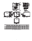
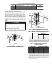
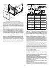
Fig. 8 — Disconnect Switch and Unit
Units Without Factory-Installed Disconnect —
When installing units, provide a disconnect switch per NEC
(National Electrical Code) of adequate size. Disconnect sizing
data is provided on the unit informative plate. Locate on unit
cabinet or within sight of the unit per national or local codes.
Do not cover unit informative plate if mounting the disconnect
on the unit cabinet.
Units with Factory-Installed Disconnect —
The factory-installed option disconnect switch is located in a
weatherproof enclosure located under the main control box.
The manual switch handle is accessible through an opening in
the access panel.
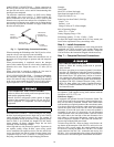
All units -
All field wiring must comply with NEC and all local codes.
Size wire based on MCA (Minimum Circuit Amps) on the unit
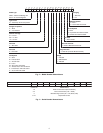
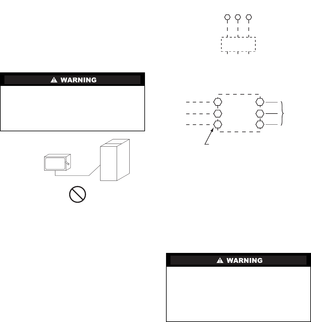
informative plate. See Fig. 9 for power wiring connections to
the unit power terminal block and equipment ground.
Maximum wire size is #4 ga AWG per pole.
Provide a ground-fault and short-circuit over-current protection
device (fuse or breaker) per NEC Article 440 (or local codes).
Refer to unit informative data plate for MOCP (Maximum
Over-current Protection) device size.
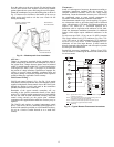
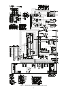
Fig. 9 — Power Wiring Connections
All field wiring must comply with the NEC and local
requirements.
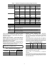
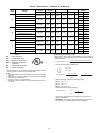
Voltage and Current Balance -
Voltage to compressor terminals during operation must be
within voltage range indicated on unit nameplate. See Table 10.
On 3-phase units, voltages between phases must be balanced
within 2% and the current within 10%. Use the formula shown
in the legend for Table 8, Note 5 (see page 14) to determine the
percent of voltage imbalance. Operation on improper line
voltage or excessive phase imbalance constitutes abuse and
may cause damage to electrical components. Such operation
would invalidate any applicable Carrier warranty.
Convenience Outlets
Two types of convenience outlets are offered on 38AUQ
models: Non-powered and unit-powered. Both types provide a
125-volt GFCI (ground-fault circuit-interrupter) duplex
receptacle rated at 15-A behind a hinged waterproof access
cover, located on the end panel of the unit. See Fig. 10.
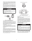
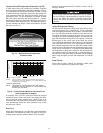
FIRE HAZARD
Failure to follow this warning could result in intermittent
operation or performance satisfaction.
Do not connect aluminum wire between disconnect switch
and condensing unit. Use only copper wire.
(See Fig. 8.)
COPPER
WIRE ONLY
ELECTRIC
DISCONNECT
SWITCH
ALUMINUM
WIRE
ELECTRICAL OPERATION HAZARD
Failure to follow this warning could result in personal
injury or death.
Units with convenience outlet circuits may use multiple
disconnects. Check convenience outlet for power status
before opening unit for service. Locate its disconnect
switch, if appropriate, and open it. Tag-out this switch, if
necessary.
11 13
L1
L2 L3
CTB1
208/230-3-60
460-3-60
575-3-60
Units Without Disconnect Option
Units With Disconnect Option
2
4
6
1
3
5
L1
L2
L3
Optional
Disconnect
Switch
Disconnect factory test leads; discard.
Factory
Wiring
Disconnect
per
NEC