


13
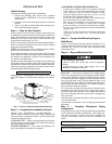
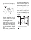
Press the gasket over the screw heads. Slip the backing plate
over the screw heads at the keyhole slots and align with the
gasket; tighten the two screws until snug (do not over-tighten).
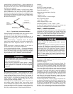
Mount the weatherproof cover to the backing plate as shown in
Fig. 12. Remove two slot fillers in the bottom of the cover to
permit service tool cords to exit the cover. Check for full
closing and latching.
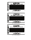
Fig. 12 — Weatherproof Cover Installation
All Units —
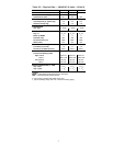
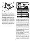
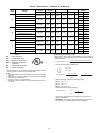
Voltage to compressor terminals during operation must be
within voltage range indicated on unit nameplate. See Table 8.
On 3-phase units, voltages between phases must be balanced
within 2% and the current within 10%. Use the formula shown
in the legend for Table 8, Note 5 (see pages 14) to determine
the percent of voltage imbalance. Operation on improper line
voltage or excessive phase imbalance constitutes abuse and
may cause damage to electrical components. Such operation
would invalidate any applicable Carrier warranty.
Field Control Wiring —
38AUQ unit control voltage is 24 v. See Fig. 19 for typical
field control connections and the unit’s label diagram for field-
supplied wiring details. Route control wires to the 38AUQ unit
through the opening in unit’s end panel to the connections
terminal board in the unit’s control box.
Remainder of the system controls connection will vary
according to the specific construction details of the indoor
section. Fig. 13 depicts typical connections to a Carrier 40RUQ
fan coil unit. Plan for field connections carefully and install
control wiring correctly per the project plan. Additional
components and supplemental transformer accessory may be
required.
The 38AUQ unit requires an external temperature control
device. This device can be a thermostat (field-supplied) or a
PremierLink controller (available as a field-installed accessory,
for use on a Carrier Comfort Network or as a stand alone
control).
Thermostat —
Install a Carrier-approved accessory thermostat according to
installation instructions included with the accessory. For
complete economizer function, select a two—stage cooling
thermostat. Locate the thermostat accessory on a solid wall in
the conditioned space to sense average temperature in
accordance with the thermostat installation instructions.
If the thermostat contains a logic circuit requiring 24-v power,
use a thermostat cable or equivalent single leads of different
colors with minimum of five leads. If the thermostat does not
require a 24-v source (no “C” connection required), use a
thermostat cable or equivalent with minimum of four leads.
Check the thermostat installation instructions for additional
features which might require additional conductors in the
cable.
For wire runs up to 50 ft. (15 m), use no. 18 AWG (American
Wire Gage) insulated wire (35°C minimum). For 50 to 75 ft.
(15 to 23 m), use no. 16 AWG insulated wire (35°C minimum).
For over 75 ft. (23 m), use no. 14 AWG insulated wire (35°C
minimum). All wire sizes larger than no. 18 AWG cannot be
directly connected to the thermostat and will require a junction
box and splice at the thermostat.
PremierLink (accessory installation) – Refer to Form 33CS-
58SI for details on connecting the PremierLink controller and
its various sensors.
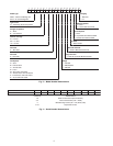
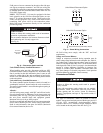
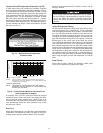
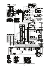
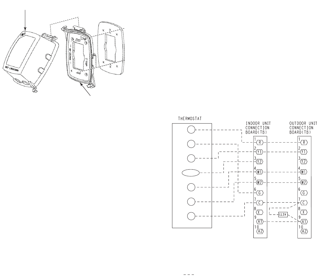
Fig. 13 — Typical Remote Thermostat Connections
RECEPTACLE
NOT INCLUDED
COVER – WHILE-IN-USE
WEATHERPROOF
BASE PLATE FOR
GFCI RECEPTACLE
Note 1: Typical multi-function marking. Follow manufacturer’s configuration
instructions to select Y2.
Note 2: Y2 to economizer required on single-stage cooling units when
integrated economizer function is desired
Note 3: Connect only if thermostat requires 24-vac power source.
Note 4: Connect W2 if supplemental heater installed
Field Wiring
R
Y1
G
O/B/Y2
C
W2
W1
(Notes 1, 2)
(Note 3)
(Note 4)