


10
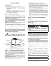
MAKE PIPING CONNECTIONS — Piping connections at
the 38AUQ unit are ball valves with stub tube extensions. Do
not open the unit service valves until all interconnecting tube
brazing as been completed.
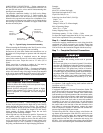
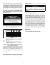
The stub tube connections include ¼-in SAE service fittings
with Schrader valve cores (see Fig. 7). Before making any
brazed connections to the unit service valves, remove both
Schrader valve caps and cores and save for re-installation. Con-
nect a source for nitrogen to one of these service fittings during
tube brazing to prevent the formation of copper oxides inside
the tubes at brazed joints.
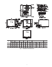
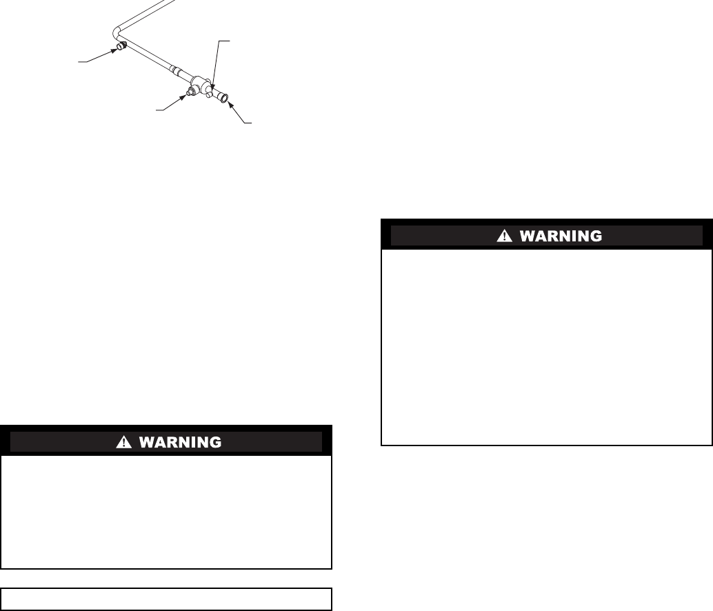
Fig. 7 — Typical Piping Connection Assembly
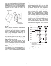
When connecting the field tubing to the 38AUQ service valves,
wrap the valves in wet rags to prevent overheating
Pressure-test all joints from outdoor unit connections over to
the indoor coil, using nitrogen as pressure and with soap-and-
bubbles.
When pressure-testing is completed, remove the nitrogen
source at the outdoor unit service valves and re-install the two
Schrader valve cores. Torque the cores to 2-3 in-lbs (23-34
N-cm).
Where vapor line is exposed to outdoor air, line must be
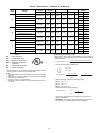
insulated. See Table 7 for insulation requirements.
EVACUATION/DEHYDRATION — Evacuate and dehydrate
the connected refrigeration system(s) (excluding the 38AUQ
unit) to 500 microns using a two-stage vacuum pump attached
to the service ports outside the 38AUQ service valves, follow-
ing description in GTAC II, Module 4, System Dehydration.
PRELIMINARY CHARGE — Before starting the unit, charge
R-410A liquid refrigerant into the high side of each 38AUQ
circuit through the liquid service valve(s). The amount of
refrigerant added must be at least 80% of the operating charge
listed in Table 2 for LINEAR line length LESS the factory
charge quantity (if factory shipping charge has not been
removed). See the following example.
Allow high and low side pressures to equalize. If pressures do
not equalize readily, charge R-410A vapor (using special
service manifold with expansion device) into the suction line
service port for the low side of system to assure charge in the
evaporator. Refer to GTAC II, Module 5, Charging, Recover,
Recycling, and Reclamation for liquid charging procedures.
Example:
38AUQ*08
60-ft (18.3 m) linear line length
Equivalent line length 90-ft (27.4 m)
Liquid Lift: 20-ft (6.1 m)
Select line sizes from Table 2 (38AUQ):
Liquid
1
/
2
in
Suction 1-
1
/
8
in.
Charge 23.0 lbs (at 75-ft linear length)
80% of Operating Charge:
0.80 x 23.0 = 17.6 lbs
Factory Shipping Charge: 12 lbs
Field-charge quantity: 17.6 lbs –12.0 lbs = 5.6 lbs
For linear line lengths longer than 100 ft (30.5 m), contact your
local Carrier representative for system charge value.
Step 6 — Install Accessories
Accessories requiring modifications to unit wiring should be
completed now. These accessories may include Winter Start
controls, Low Ambient controls, phase monitor, Compressor
LOCout. Refer to the instructions shipped with the accessory.
Step 7 — Complete Electrical Connections
NOTE: Check all factory and field electrical connections
for tightness. Field-supplied wiring shall conform with the
limitations of 63°F (33°C) rise.
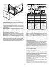
Field Power Supply —
If equipped with optional Powered Convenience Outlet: The
power source leads to the convenience outlet's transformer pri-
mary are not factory connected. Installer must connect these
leads according to required operation of the convenience outlet.
If an always-energized convenience outlet operation is desired,
connect the source leads to the line side of the unit-mounted
disconnect. (Check with local codes to ensure this method is
acceptable in your area.) If a de-energize via unit disconnect
switch operation of the convenience outlet is desired, connect
the source leads to the load side of the unit disconnect. On a
unit without a unit-mounted disconnect, connect the source
leads to compressor contactor C and indoor fan contactor IFC
pressure lugs with unit field power leads.
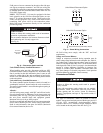
All units except 208/230-v units are factory wired for the volt-
age shown on the nameplate. If the 208/230-v unit is to be con-
nected to a 208-v power supply, the control transformer must
be rewired by moving the black wire with the 1/4-in. female
spade connector from the 230-v connection and moving it to
the 208-v 1/4-in. male terminal on the primary side of the trans-
former. Refer to unit label diagram for additional information.
UNIT OPERATION AND SAFETY HAZARD
Failure to follow this warning could cause personal injury,
death and/or equipment damage.
Puron® (R-410A) refrigerant systems operate at higher
pressures than standard R-22 systems. Do not use R-22
service equipment or components on Puron refrigerant
equipment.
IMPORTANT: Charge in Cooling mode only!
Factory
High-Flow
Access Port
Service Valve
with Stem Cap
Field Service
Access Port
(Schrader core)
Sweat
Connection
ELECTRICAL SHOCK HAZARD
Failure to follow this warning could result in personal
injury or death.
Do not use gas piping as an electrical ground. Unit cabinet
must have an uninterrupted, unbroken electrical ground to
minimize the possibility of personal injury if an electrical
fault should occur. This ground may consist of electrical
wire connected to unit ground lug in control compartment,
or conduit approved for electrical ground when installed in
accordance with NEC (National Electrical Code); ANSI/
NFPA 70, latest edition (in Canada, Canadian Electrical
Code CSA [Canadian Standards Association] C22.1), and
local electrical codes.