


16
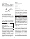
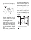
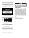
Advanced Scroll Temperature Protection (ASTP)
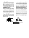
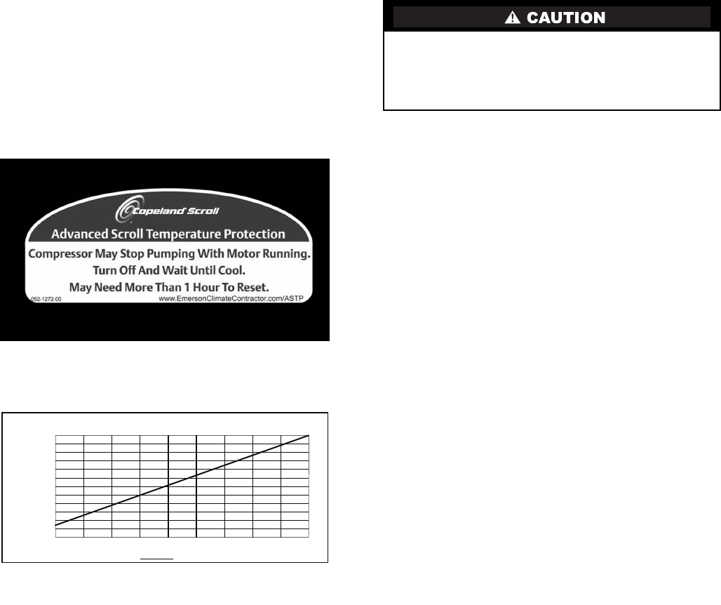
A label located above the terminal box identifies Copeland
Scroll compressor models that contain this technology. See Fig.
14. Advanced Scroll Temperature Protection (ASTP) is a form
of internal discharge temperature protection, that unloads the
scroll compressor when the internal temperature reaches ap-
proximately 300°F. At this temperature, an internal bi-metal
disk valve opens and causes the scroll elements to separate,
which stops compression. Suction and discharge pressures bal-
ance while the motor continues to run. The longer the compres-
sor runs unloaded, the longer it must cool before the bi-metal
disk resets. See Fig. 15.
Fig. 14 — Advanced Scroll Temperature
Protection Label
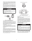
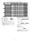
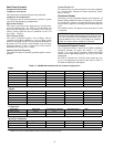
Fig. 15 — Recommended Minimum Cool-Down Time
After Compressor is Stopped
To manually reset ASTP, the compressor should be stopped
and allowed to cool. If the compressor is not stopped, the motor
will run until the motor protector trips, which occurs up to
90 minutes later. Advanced Scroll Temperature Protection will
reset automatically before the motor protector resets, which
may take up to 2 hours.
Start Unit
Set the space thermostat to a set point above space temperature
so that there is no demand for cooling. Close the 38 AUQ dis-
connect switch. Only the crankcase heater will be energized.
Reset the space thermostat below ambient so that a call for
cooling is ensured.
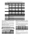
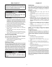
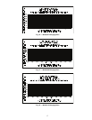
Adjust Refrigerant Charge
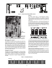
The unit must be charged in Cooling mode only. Refer to Cool-
ing Charging Charts, Fig. 16 through Fig. 18. For applications
with line lengths greater than 100 ft, contact Carrier representa-
tive. Vary refrigerant until the conditions of the chart are met.
The charts are based on charging the units to the correct sub-
cooling for the various operating conditions. Accurate pressure
gage and temperature sensing device are required. Connect the
pressure gage to the service port on the liquid line service
valve. Mount the temperature sensing device on the liquid line
close to the liquid line service valve, and insulate it so that out-
door ambient temperature does not affect the reading. Indoor
airflow must be within the unit’s normal operating range. Oper-
ate the unit for a minimum of 15 minutes. Ensure that pressure
and temperature readings have stabilized. Plot the liquid pres-
sure and temperature on chart and add or reduce the charge to
meet the curve. Adjust the charge to conform with the charging
chart, using the liquid pressure and temperature to read the
chart.
Final Checks
Ensure that all safety controls are operating, control panel
covers are on, and the service panels are in place.
0
10
20
30
40
50
60
70
80
90
100
110
120
0 10 20 30 40 50 60 70 80 90
Compressor Unloaded Run Time (Minutes)
Recommended Cooling Time
(Minutes)
*Times are approximate.
NOTE: Various factors, including high humidity, high ambient
temperature, and the presence of a sound blanket will
increase cool-down times.
*Times are approximate.
NOTE: Various factors, including high humidity, high ambient
temperature, and the presence of a sound blanket will
increase cool-down times.
Never charge liquid into the low-pressure side of system.
Do not overcharge. During charging or removal of refriger-
ant, be sure indoor-fan system is operating. Ensure both
outdoor fan motors are running; bypass any Motormaster
function.