


8
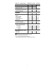
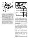
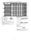
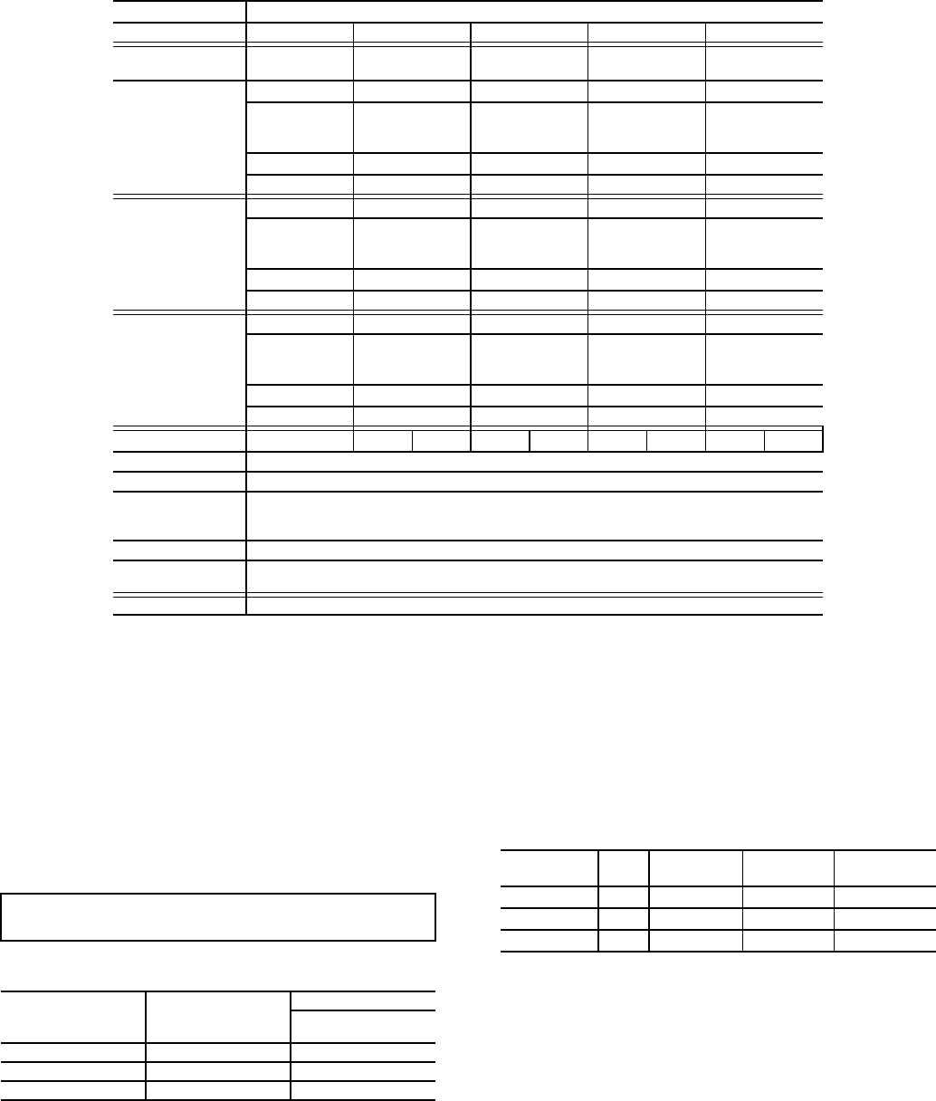
Table 2 — 38AUQ*07-12 Piping Recommendations (Single-Circuit Unit)
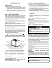
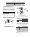
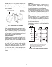
CHECK VERTICAL SEPARATION — If there is any vertical
separation between the indoor and outdoor units, check to
ensure that the separation is within allowable limits. Relocate
equipment if necessary.
PROVIDE SAFETY RELIEF — If local codes dictate an
additional safety relief device, purchase locally and install
locally. Installation will require the recovery of the factory
shipping charge before the factory tubing can be cut and the
supplemental relief device is installed.
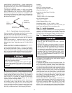
REFRIGERANT LINE SIZING — Consider the length of
the piping required between the outdoor and indoor units. The
maximum allowable line length is 100 ft (30.5 m). See Table 2.
Refrigerant vapor piping should be insulated.
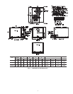
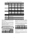
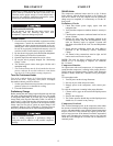
Table 3 — Maximum Vertical Separation*
*Vertical distance between indoor and outdoor units.
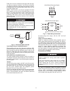
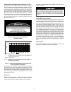
INSTALL FILTER DRIER(S) AND MOISTURE
INDICATOR(S) — Every unit MUST have a bi-directional
filter drier in the liquid line. Locate the filter drier at the indoor
unit, close to the evaporator coil’s thermal expansion valve
(TXV) inlets.
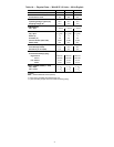
38AUQ units include one Puron-duty filter drier, shipped in
cartons attached to the unit basepan. Remove the filter drier
and prepare to install in the liquid line at the evaporator coil.
Do not remove connection fitting plugs until ready to connect
and braze the filter drier into the liquid line position.
Table 4 — Puron-duty Filter Drier(s)
Installation of liquid line moisture indicating sightglass in each
circuit is recommended. Locate the sightglass(es) between the
outlet of the filter drier and the TXV inlet.
Refer to Table 5 for recommendations on refrigeration
specialties.
Select the filter drier for maximum unit capacity and minimum
pressure drop. Complete the refrigerant piping from the indoor
unit to the outdoor unit before opening the liquid and suction
lines at the outdoor unit.
R-410A Equivalent Length
Ft 0-38 38-75 75-113 113-150
Model
Nominal Capacity
Length Linear
Length Equiiv
0-25
0-38
25-50
38-75
50-75
75-113
75-100
113-115
38AUQ*07 Liquid Line
3
/
8
3
/
8
3
/
8
1
/
2
3
/
8
1
/
2
Max Lift
Cool
Heat
25
25
50
50
48
46
75
60
39
31
100
60
Suction Line
7
/
8
7
/
8
1-
1
/
8
1-
1
/
8
Charge (lbs) 17.8 18.8 20.3 22.6 21.4 24.5
38AUQ*08 Liquid Line
1
/
2
1
/
2
1
/
2
1
/
2
Max Lift
Cool
Heat
25
25
50
50
75
60
100
60
Suction Line
7
/
8
1-
1
/
8
1-
1
/
8
1-
1
/
8
1-
1
/
8
Charge (lbs) 20.9 23.0 24.9 26.8
38AUQ*12 Liquid Line
1
/
2
1
/
2
1
/
2
1
/
2
5
/
8
Max Lift
Cool
Heat
25
25
50
50
75
60
85
60
100
60
Suction Line
7
/
8
1-
1
/
8
1-
1
/
8
1-
1
/
8
1-
1
/
8
1-
3
/
8
Charge (lbs) 26.8 28.8 30.7 33.4 37.2
Legend:
Length Equiv Equivalent tubing length, including effects of refrigeration specialties devices
Liquid Line Tubing size, inches OD.
Max Lift
Cooling
Heating
Maximum liquid lift at maximum permitted liquid line pressure drop
• Indoor unit ABOVE outdoor unit
• Indoor unit BELOW outdoor unit
Suction Line Tube size, inches OD
Charge Charge Quantity, lbs. Calculated for both liquid line sizes (where applicable), but only with larger
suction line size (where applicable)
NOTE:
For applications with linear length greater than 100 ft (30.5 m), contact your local Carrier representative.
IMPORTANT: A refrigerant receiver is not provided
with the unit. Do not install a receiver.
UNIT 38AUQ UNIT 40RUQ
DISTANCE FT (M)
Unit 38AUQ
Above Unit 40RMQ
07 07 50 (15.2)
08 08 60 (18.3)
12 12 60 (18.3)
Model-Size Qty
Liquid
Line OD
Desiccant
Volume
Part
Number Ref
38AUQ*07 1
3
/
8
-in 8 cu. in. KH43LG091
38AUQ*08 1
1
/
2
-in 16 cu. in. KH43LG085
38AUQ*12 1
1
/
2
-in 16 cu. in. KH43LG085