


21
Liquid Line Filter Drier
The factory-provided reversible filter drier is specifically de-
signed to operate with Puron®. Replace the filter drier with
factory-authorized components only with a filter drier with
desiccant made from 100% molecular sieve grade XH-11. Fil-
ter drier must be replaced whenever the refrigerant system is
opened.
When removing a filter drier, use a tubing cutter to cut the drier
from the system. Do not unsweat a filter drier from the sys-
tem. Heat from unsweating will release moisture and contami-
nants from drier into system.
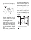
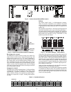
Field Refrigerant Access Ports
Field service access to refrigerant pressures is through the
access ports located at the service valves (see Figs 24, 26 and
28). These ports are ¼-in SAE Flare couplings with Schrader
check valves and service caps. Use these ports to admit
nitrogen to the field tubing during brazing, to evacuate the
tubing and evaporator coil, to admit initial refrigerant charge
into the low-side of the system and when checking and
adjusting the system refrigerant charge. When service activities
are completed, ensure the service caps are in place and secure;
check for leaks. If the Schrader check valve must be removed
and re-installed, tighten to 2-3 in-lbs (23-34 N-cm).
Outdoor Coil Metering Devices
The metering devices are multiple fixed–bore devices (Acu-
trol™) swaged into the horizontal outlet tubes from the liquid
header, located at the entrance to each evaporator coil circuit
path. These are non–adjustable. Service requires replacing the
entire liquid header assembly.
To check the indoor coil, disconnect the supply fan signal
(A04-A06 direct-drive fans) or contactor (IFC) coil, then start
the circuit in a Cooling Mode (jumper R to Y1 or Y2) and ob-
serve the frosting pattern on the face of the indoor coil. A frost
pattern should develop uniformly across the face of the indoor
coil starting at each tube at the Acutrol nipple locations.
To check the outdoor coil, disconnect the outdoor fan motor.
Start the circuit in a Heating Mode (jumper R to W1 or W2)
and observe the frost pattern on the face of the outdoor coil.
Failure to develop frost at an outlet tube can indicate a plugged
or a missing orifice.
Refrigerant System Pressure Access Ports
There are two access ports in each circuit - on the suction tube
near the compressor and on the discharge tube near the com-
pressor. These are brass fittings with black plastic caps. The
hose connection fittings are standard 1/4 SAE Male Flare cou-
plings.
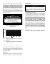
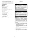
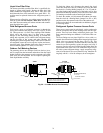
The brass fittings are two-piece High Flow valves, with a re-
ceptacle base brazed to the tubing and an integral spring-closed
check valve core screwed into the base. (See Fig. 20.) This
check valve is permanently assembled into this core body and
cannot be serviced separately; replace the entire core body if
necessary. Service tools are available from RCD that allow the
replacement of the check valve core without having to recover
the entire system refrigerant charge. Apply compressor refrig-
erant oil to the check valve core's bottom o-ring. Install the fit-
ting body with 96 +/-10 in-lbs of torque; do not overtighten.
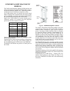
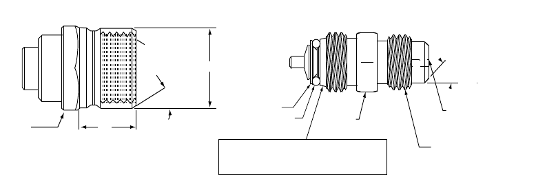
Fig. 20 — CoreMax Access Port Assembly
1/2-20 UNF RH
30°
0.596
.47
5/8” HEX
SEAT
CORE
WASHER
DEPRESSOR PER ARI 720
+.01/-.035
FROM FACE OF BODY
7/16-20 UNF RH
O-RING
45°
1/2" HEX
This surface provides a metal to metal seal when
torqued into the seat. Appropriate handling is
required to not scratch or dent the surface.
(Part No. EC39EZ067)