


19
OPERATING SEQUENCE
Base Unit Controls —
Indoor (Supply) Fan
The indoor fan contactor (IFC) is remotely located at the fan
coil or fan section. If the thermostat fan operation is selected as
Continuous, the IFC is energized and the indoor (supply) fan
motor runs continuously. If the thermostat fan operation is
selected as Automatic, the IFC will be energized on a call for
Cooling or Heating; indoor (supply) fan motor runs. When
thermostat is satisfied, the IFC is de-energized and indoor
(supply) fan motor stops.
Cooling, Unit Without Economizer
When thermostat calls for Cooling, terminal Y1 is energized.
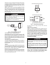
The 38AUQ’s Defrost Board (DFB) receives this input at P2-5.
DFB issues 24-v outputs at OF, P3-7 (RVS1) and P3-10
(COMP1). The OF output energizes outdoor fan relay (OFR);
both outdoor fan motors start and run. The output RVS1 ener-
gizes the reversing valve solenoid (RVS); Reversing valve
switches to Cooling position.
Output PL3-10 (COMP1, 24-v) is received at CADM terminal
Y. If anti-recycle time delay period has not expired, safety pres-
sure switches are open, and/or lockout alarms are active,
CADM relay will remain open, preventing compressor start.
When safety pressure switches are closed and CADM time de-
lay expires, the CADM relay closes, energizing Solenoid Valve
Relay SVR and compressor contactor C. SVR contacts close,
energizing the external liquid line solenoid valve. Solenoid
valve LLSV opens. Compressor contactor C closes, energizing
the compressor motor. Compressor starts and system runs in
Cooling mode.
When space cooling load is satisfied, terminal Y1 is de-enger-
ized. Compressor and outdoor fan motors stop. Liquid line so-
lenoid valve LLSV is de-energized and valve closes. CADM
begins its three-minute anti-recycle time delay.
If either the Loss of Charge (LOC) Switch or High Pressure
Switch (HPS) opens while Y1 remains energized, the compres-
sor contactor C and relay SVR are de-energized; compressor
stops and liquid line solenoid is de-energized (valve closes).
CADM initiates a TRIP event (cooling demand sensed at
CADM terminal Y but no current is measured at T1, T2, T3
motor sensors); CADM relay opens and RED LED is illumi-
nated. TRIP condition maintains lockout of compressor opera-
tion until CADM is manually reset. Reset CADM by cycling
unit main power.
Reversing valve solenoid (RVS) is energized in Cooling
modes. This solenoid will remain energized until the next Heat-
ing mode is initiated.
Cooling, Unit With Economizer
Refer to fan coil unit installation instructions and economizer
accessory installation instructions for operating sequences
when system is equipped with accessory economizer.
Heating
When the thermostat calls for first stage heating, terminal W1
is energized. The 38AUQ’s Defrost Board (DFB) receives this
input at P2-7. The DFB removes the output at P3-7 (RVS1); the
reversing valve solenoid is de-energized and the reversing
valve moves to Heating position.
DFB issues outputs at OF and P3-10 (COMP1). Outdoor fan
relay OFR is energized; both outdoor fan motors run.
Output PL3-10 (COMP1, 24-v) is received at CADM terminal
Y. If anti-recycle time delay period has not expired and/or
safety pressure switches are open, outdoor lockout alarms are
active, CADM relay will remain open, preventing compressor
start. When safety pressure switches are closed and CADM
time delay expires, the CADM relay closes, energizing
Solenoid Valve Relay SVR and compressor contactor C.SVR
contacts close, energizing the external liquid line solenoid
valve. Solenoid valve LLSV opens. Compressor contactor C
closes, energizing the compressor motor. Compressor starts
and system runs in Heating mode, providing Stage 1 Heat.
When the space heating load is satisfied terminal W1 is
de-energized. Compressor and outdoor fan operations stop.
Liquid line solenoid LLSV is de-energized and valve closes.
CADM begins its three-minute anti-recycle time delay.
If either the Loss of Charge (LOC) Switch or High Pressure
Switch (HPS) opens while, the compressor contactor C and re-
lay SVR are de-energized; compressor stops and liquid line so-
lenoid is de-energized (valve closes). CADM initiates a TRIP
event (compressor demand sensed at CADM terminal Y but no
current is measured at T1, T2, T3 motor sensors); CADM relay
opens and RED LED is illuminated. TRIP condition maintains
lockout of compressor operation until CADM is manually re-
set. Reset CADM by cycling unit main power.
Reversing valve solenoid remains de-energized until the next
Cooling cycle is initiated.
Defrost Cycle
During the Heating Mode, frost and ice can develop on the out-
door coil. Defrost sequence will clear the frost and ice from the
coil by briefly reversing the Heating sequence periodically.
A window to test for a need to run the Defrost cycle opens at a
fixed period after the end of the last Defrost cycle or the previ-
ous test window closed. The window period is determined by
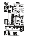
the configuration settings on the DFB’s DIP switches (see unit
wiring diagram).
If the outdoor coil’s Defrost Thermostat switch (DFT) is closed
(shorting DFB terminals DFT1 and DFT1), the Defrost cycle
will start. Output at OF is removed; outdoor fans stop during
the Defrost cycle. Output P3–7 (RVS1) is energized; reversing
valve solenoid RVS is energized and reversing valve changes
position, placing the circuit in a Cooling mode flow, directing
hot gas into the outdoor coil where its heat melts the frost and
loosens the ice on the coil face.
During the Defrost cycle, output EHEAT is also energized (if
not already energized by a thermostat W2 demand); supple-
mental heater will be energized. During the Defrost Cycle,
LED1 on the DFB will be illuminated. The Defrost cycle ends
when DFT opens (as liquid temperature exiting the coil rises
above DFT setpoint) or the defrost cycle runs for 10 minutes.
Output at EHEAT is removed; supplemental heater will be
de-energized (unless thermostat has a W2 demand). Output at
OF is restored; outdoor fans start again. Output P3–7 (RVS1) is
removed; reversing valve returns to Heating position.
Defrost cycle is fixed at a maximum 10 minute duration limit.
The period to test and initiate a Defrost cycle can be configured
for 30, 60, 90 or 120 minutes.
Supplemental Heat/Emergency Heat
Supplemental heat type is determined by 40RUQ indoor unit
options and accessories. This heat is initiated when the indoor
unit W2 terminal is energized by the thermostat. (Or as detailed
in “Defrost Cycle” on page 19.) The thermostat may energizes
W2 as supplemental (2nd stage) heat at larger space heating de-
mand, or when selected as emergency heat mode. When the
space heating demand decreases below the 2nd stage limit, or
emergency heat is turned off, W2 is de-energized, and supple-
mental heat is turned off.
Cooling and Heating Shutdown
Partial or complete cooling or heating functions may shutdown
caused by loss of main power, open pressure switches, diag-
nostic alarms, or open internal compressor protections. See
Service section for further details.