


30
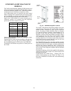
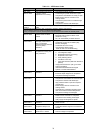
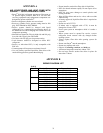
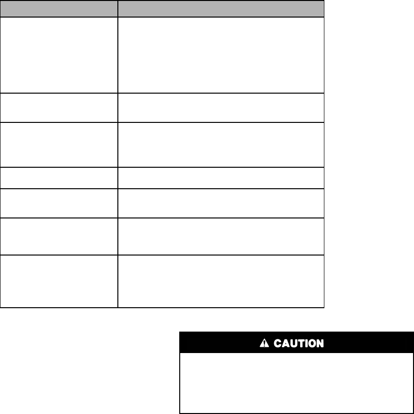
Table 15 — CADM Troubleshooting
Lubrication
FAN MOTORS have sealed bearings. No provisions are made
for lubrication.
COMPRESSOR has its own oil supply. Loss of oil due to a
leak in the system should be the only reason for adding oil after
the system has been in operation.
Outdoor Coil Maintenance and Cleaning
Recommendation
Routine cleaning of coil surfaces is essential to maintain proper
operation of the unit. Elimination of contamination and remov-
al of harmful residues will greatly increase the life of the coil
and extend the life of the unit. The following maintenance and
cleaning procedures are recommended as part of the routine
maintenance activities to extend the life of the coil.
Remove Surface Loaded Fibers
Surface loaded fibers or dirt should be removed with a vacuum
cleaner. If a vacuum cleaner is not available, a soft non-metallic
bristle brush may be used. In either case, the tool should be
applied in the direction of the fins. Coil surfaces can be easily
damaged (fin edges can be easily bent over and damage the
coating of a protected coil) if the tool is applied across the fins.
NOTE: Use of a water stream, such as a garden hose,
against a surface loaded coil will drive the fibers and dirt
into the coil. This will make cleaning efforts more difficult.
Surface loaded fibers must be completely removed prior to
using low velocity clean water rinse.
Periodic Clean Water Rinse
A periodic clean water rinse is very beneficial for coils that are
applied in coastal or industrial environments. However, it is
very important that the water rinse is made with very low ve-
locity water stream to avoid damaging the fin edges. Monthly
cleaning as described below is recommended.
Routine Cleaning of Indoor Coil Surfaces
Periodic cleaning with Totaline
®
environmentally sound coil
cleaner is essential to extend the life of coils. This cleaner is
available from Carrier Replacement Components Division as
part number P902-0301 for one gallon container, and part num-
ber P902-0305 for a 5 gallon container. It is recommended that
all coils, including standard aluminum, pre-coated, copper/cop-
per or E-coated coils be cleaned with the Totaline environmen-
tally sound coil cleaner as described below. Coil cleaning
should be part of the unit's regularly scheduled maintenance
procedures to ensure long life of the coil. Failure to clean the
coils may result in reduced durability in the environment.
Avoid the use of
• coil brighteners
• acid cleaning prior to painting
• high pressure washers
• poor quality water for cleaning
Totaline environmentally sound coil cleaner is nonflammable,
hypoallergenic, non bacterial, and a USDA accepted biode-
gradable agent that will not harm the coil or surrounding com-
ponents such as electrical wiring, painted metal surfaces, or in-
sulation. Use of non-recommended coil cleaners is strongly
discouraged since coil and unit durability could be affected.
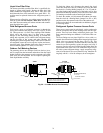
Miswired Module Indication Recommended Troubleshooting Action
Green LED is not on,
module does not power up
Determine if both R and C module terminals are
connected. Verify voltage in present at module’s R and C
terminals.
NOTE: The CADM requires a constant nominal 24VAC
power supply. The wiring to the module’s R and C
terminals must be directly from the control transformer.
The module cannot receive its power from another device
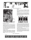
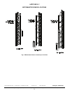
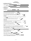
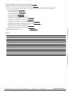
that will interrupt the 24VAC power supply. See Fig. 19,
the 38AUQ Wiring Diagram.
Green LED Intermittent,
module powers up only
when compressor runs
Determine if R and Y terminals are wired in reverse. Verify
module’s R and C terminals have a constant source. See
“NOTE” above for details on R and C wiring.
TRIP LED is on but system
and compressor check OK
Verify Y terminal is wired properly per the 38AUQ wiring
diagram (see Fig. 19). Verify voltage at contactor coil falls
below 0.5VAC when off. Verify 24VAQC is present across
Y and C when thermostat demand signal is present. If not,
R and C are reverse wired.
TRIP LED and ALERT LED
flashing together
Verify R and C terminals are supplied with 19-28VAC.
ALERT Flash Code 3
(Compressor Short Cycling)
displayed incorrectly
Verify Y terminal is connected to 24VAC at contactor coil.
Verify voltage at contactor coil falls below 0.5VAC when
off.
ALERT Flash Code 5 or 6
(Open Circuit, Missing Phase)
displayed incorrectly
Check that compressor T1 and T3 wires are through
module’s current sensing holes. Verify Y terminal is
connected to 24VAC at contactor coil. Verify voltage at
contactor coil falls below 0.5VAC when off.
Alert Flash Code *
(Welded Contactor)
displayed incorrectly
Determine if module’s Y terminal is connected. Verify Y
terminal is connected to 24VAC at contactor coil. Verify
24VAC is present across Y and C when thermostat
demand signal is present. If not, R and C are reverse
wired. Verify voltage at contactor coil falls below 0.5VAC
when off.
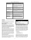
PERSONAL INJURY AND UNIT DAMAGE
HAZARD
Failure to follow this caution may result in personal injury
or equipment damage.
Only approved cleaning is recommended.