


7
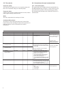
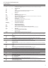
Description
Alarm relay output
circuit A
Alarm relay output
circuit B
Boiler relay output
Contact 1:
start/stop/heat/cool
Contact 2:
start/stop/heat/cool
Contact 3:
demand limit selection
Contact 4:
demand limit selection
Contact 5:
setpoint selection
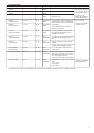
Control contact 6:
setpoint selection
User safety loop input
Connection to CCN
Connector/channel
J3 / CH24
J3 / CH24
J3 / CH25
J4 / CH8
J4 / CH9
J4 / CH10
J4 / CH10
J4 / CH8
J4 / CH9
J4 / CH11a
J12
Terminal
30A - 31A
30B - 31B
37 - 38
32 - 33
63 - 64
73 - 74
75 - 76
65 - 66
67 - 68
34 - 35
1 - 2 - 3
Board
Master NRCP-
BASE
Slave NRCP-
BASE
Master NRCP-
BASE
Master NRCP-
BASE
Master NRCP-
BASE
Master NRCP-
BASE
Slave
NRCP-BASE
Slave
NRCP-BASE
Slave
NRCP-BASE
Master
NRCP-BASE
Master
NRCP-BASE
Remarks
Indicates alarms/alerts for circuit A*
Indicates alarms/alerts for circuit B*
Boiler start/stop control output.
See section 5.13.
The contacts are used for unit start/stop and
heat/cool control. They are only taken into
account if the unit is under remote operation
control (rEM).
See the description of these contacts in
sections 3.6.2 and 3.6.3.
These dry contacts are used for demand
limit selection. See description of these
contacts in section 3.6.5.
The remote demand limit selection contact is
active whatever the operating type of the
unit.
These dry contacts are used for setpoint
selection.
They are only taken into account if the unit is
in remote control operating type (rEM).
See the description of these contacts in
sections 3.6.6.
This contact is mounted in series with the
water flow control contact. It can be used for
any customer safety loop that requires that
the unit is stopped, if it is open.
If it is unused this contact must be bridged.
An RS-485 bus is used for connection to the
CCN.
- Pin 1: signal +
- Pin 2: ground
- Pin 3: signal -
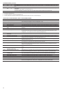
Remarks
Volt-free contact 24 V a.c.
48 V d.c. max, 20 V a.c. or
V d.c., 3 A max, 80 mA min,
external power supply.
Connector: 4 pin
WAGO 734-104 pitch 3.5.
One per board needed.
24 V a.c., 20 mA
Connector: 8 pin WAGO
734-168, pitch 3.5
Connector: 3 pin WAGO
231-303, pitch 5.08
DUAL-CIRCUIT UNITS
* The operation of these relays can vary depending on the user configuration. See section ‘Description of the User 2 configuration sub-menu’.