


14
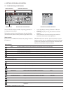
MENU
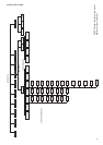
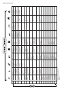
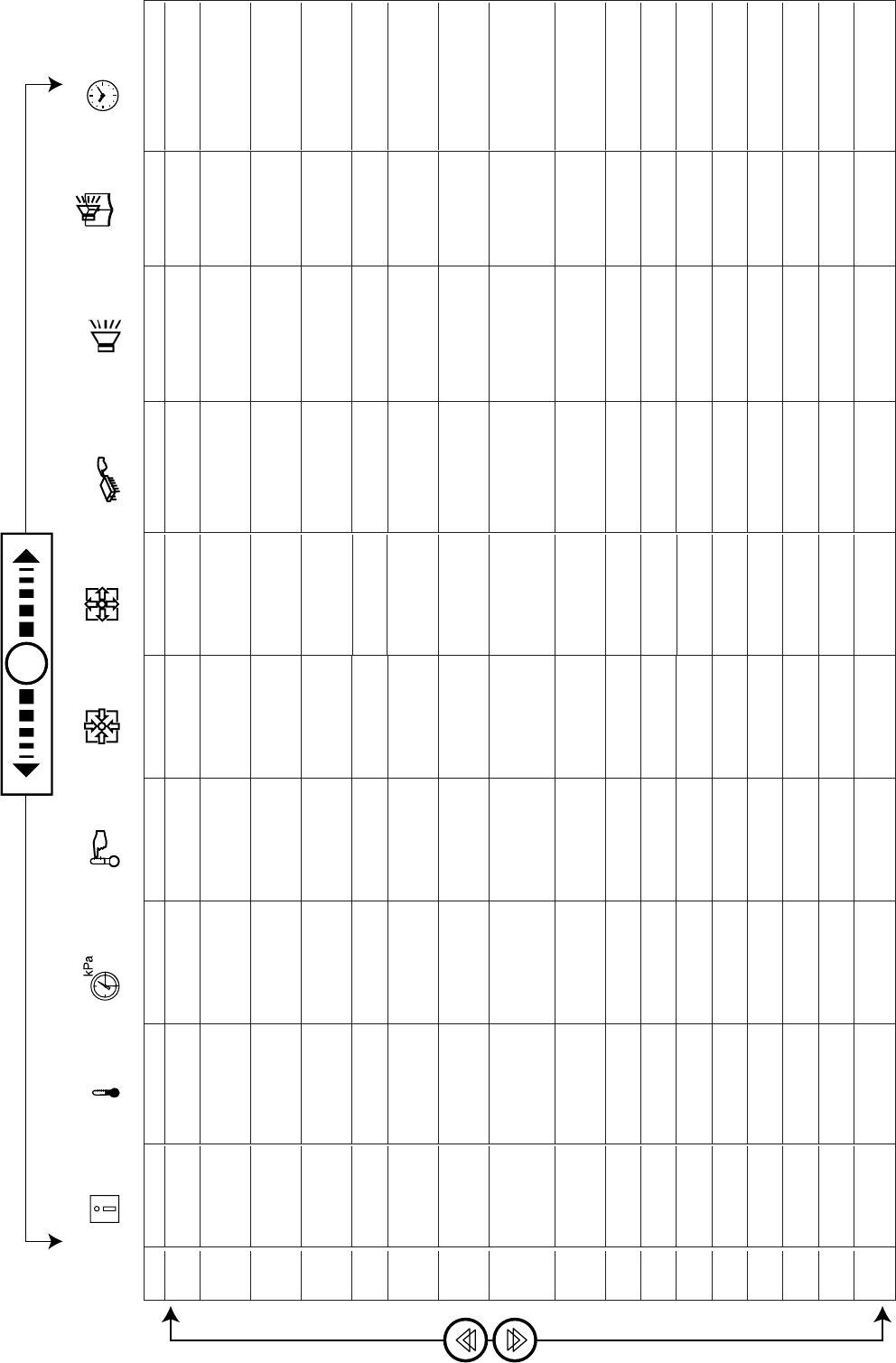
Menu tree structure
Legend
* Displayed if the configuration requires it
** Displayed if the alarm exists
- Not in use
ITEM
0
1
2
3
4
5
6
7
8
9
10
11
12
13
14
15
16
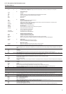
STATUS
Default display
Mode
Chiller occupied
mode*
Minutes left
Cooling/heating
selection*
Cooling/heating
status*
Unit capacity in
%
Capacity circuit
A in %*
Capacity circuit
B in %*
Heater stages in
%*
Present demand
limit in %
Present lag limit
in %*
Setpoint in local
control*
Setpoint
occupied mode*
Active setpoint
Control point
Controlled water
temperature
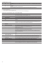
TEMP
Evaporator water
entering temp.
Evaporator water
leaving temp.
Outdoor tempera-
ture
Saturated discharge
temperature circuit
A
Saturated suction
temp. circuit A
Saturated discharge
temperature circuit
B*
Saturated suction
temp. circuit B*
Defrost temperature,
circuit A*
Defrost temperature,
circuit B*
System water
temperature*
-
-
-
-
-
-
-
PRESSURES
Discharge pressure
circuit A
Suction pressure
circuit A
Discharge pressure
circuit B*
Suction pressure
circuit B*
-
-
-
-
-
-
-
-
-
-
-
-
-
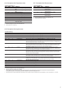
SETPOINTS
Cooling setpoint 1
Cooling setpoint 2
Heating setpoint 1*
Heating setpoint 2*
Heating setpoint 3*
Auto changeover
threshold (heating
mode)*
Auto changeover
threshold (cooling
mode)*
Setpoint demand
limitation 1*
Setpoint demand
limitation 2*
Setpoint demand
limitation 3*
Ramp loading*
Cooling - zero reset
threshold*
Cooling - full reset
threshold*
Cooling - full reset
value*
Heating - zero reset
threshold*
Heating - full reset
threshold*
Heating - full reset
value*
INPUTS
Contact 1: on/off/
heating/cooling
Contact 2: on/off/
heating/cooling
Contact 3: demand
limit/setpoint
selection
Contact 4: demand
limit selection*
Contact 5: setpoint
selection*
Contact 6: setpoint
selection*
Safety loop status
Water pump
operation contact
status*
Fault contact, com-
pressor, circuit A*
Fault contact, com-
pressor, circuit B*
-
-
-
-
-
-
-
OUTPUTS
Compressor status
circuit A
Compressor status
circuit B*
Two-speed fan
status circuit A
Two-speed fan
status circuit B*
Single-speed fan
status, crt A + B*
Water pump 1
status*
Water pump 2
status*
Water heat
exchanger + air heat
exchanger heater
status, circuit A
-
Alarm circuits A and
B status
Boiler status*
Speed, fan A in %*
Speed, fan B in %*
Reversing valve,
circuit A*
Reversing valve,
circuit B*
Status, heater
stages*
Local interface test
CONFIG
SUB-MENU: User
Configuration (USEr)
SUB-MENU:
Service Configuration
(SErviCE)
SUB-MENU:
Factory Configuration
(FACtorY)
-
-
-
-
-
-
-
-
-
-
-
-
-
-
ALARMS
Number of active
alarms/resets**
Active alarm code 1**
Active alarm code 2**
Active alarm code 3**
Active alarm code 4**
Active alarm code 5**
-
-
-
-
-
-
-
-
-
-
-
ALARMS HIST
Historic alarm code
1**
Historic alarm code
2**
Historic alarm
code 3**
Historic alarm code
4**
Historic alarm code
5**
Historic alarm code
6**
Historic alarm code
7**
Historic alarm code
8**
Historic alarm code
9**
Historic alarm code
10**
-
-
-
-
-
-
-
RUNTIMES
SUB-MENU:
Runtimes 1
SUB-MENU:
Runtimes 2
SUB-MENU:
Maintenance
-
-
-
-
-
-
-
-
-
-
-
-
-
-