


17
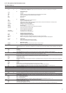
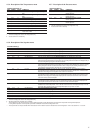
SETPOINTS MENU [2]
ITEM FORMAT UNITS RANGE
0 ±nn.n °C See table below
1 ±nn.n °C See table below
2 nnn °C See table below
3 [1] nnn °C See table below
4 [1] nn.n °C See table below
5 [1] ±nn.n °C 3.8 to 50
6 [1] ±nn.n °C 0 to 46
7 nnn % 0 to 100
8 [1] nnn % 0 to 100
9 [1] nnn % 0 to 100
10 ±nn.n °C/min 0.1 to 1.1
11 [1] ±nn.n °C See table below
12 [1] ±nn.n °C See table below
13 [1] ±nn.n °C See table below
14 [1] ±nn.n °C See table below
15 [1] ±nn.n °C See table below
16 [1] ±nn.n °C -16 to 16
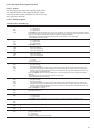
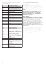
4.3.8 - Description of the Setpoints menu
1 This item is displayed in certain unit configurations only.
2 All points contained in this table can be modified.
* Those setpoints can be used for entering or leaving water temperature control. By default the unit controls the evaporator entering fluid temperature.
Leaving fluid temperature control requires a parameter modification in the Service Configuration menu.
** These parameters are only accessible when reset based on OAT or delta T has been selected in the User Configuration 1 menu. See section 4.3.11.3 & 5.6.2.
COMMENTS
This item lets you display and modify Cooling setpoint 1*
This item lets you display and modify Cooling setpoint 2*
This item lets you display and modify Heating setpoint 1*, only displayed for heat pumps.
This item lets you display and modify Heating setpoint 2*, only displayed for heat pumps.
This item lets you display and modify Heating setpoint 3*, only displayed for heat pumps.
Automatic changeover threshold, cooling mode. This item lets you display and modify the outdoor
temperature threshold at which the unit changes over in cooling mode. See section 5.2. Displayed only if
the auto cooling/heating changeover function is selected.
Automatic changeover threshold, heating mode. This item lets you display and modify the outdoor
temperature threshold at which the unit changes over in heating mode. Displayed only if the auto cooling/
heating changeover function is selected and if the unit is a heat pump. The heating threshold must be
3.8°C below the cooling threshold, otherwise the new setpoint will be rejected.
Demand limit 1 setpoint. Limitation by volt-free contact. This item is used to define the maximum
capacity that the unit is authorised to use, if the demand limit contact(s) activate limit 1. Contact control
depends on the unit type and configuration. See sections 3.6.4 and 3.6.5.
Demand limit 2 setpoint. Limitation by volt-free contact. This item is used to define the maximum
capacity that the unit is authorised to use, if the demand limit contact(s) activate limit 2. Contact control
depends on the unit type and configuration. Displayed and used only for dual-circuit units. See section
3.6.5 for the contact control description.
Demand limit 3 setpoint. Limitation by volt-free contact. This item is used to define the maximum
capacity that the unit is authorised to use, if the demand limit contact(s) activate limit 3. Displayed and
used only for dual-circuit units. See section 3.6.5 for the contact control description.
Cooling or heating ramp loading rate. This parameter is only accessible if the ramp function is
validated in the User Configuration 1 menu. This item refers to the rates of temperature drop in °C in the
evaporator. When capacity loading is effectively limited by the ramp, mode 7 is active.
Zero reset threshold, cooling mode**
Full reset threshold, cooling mode**
Full reset value, cooling mode**
Zero reset threshold, heating mode**
Full reset threshold, heating mode**
Full reset value, heating mode**
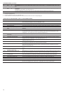
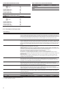
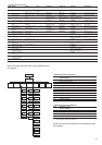
4.3.6 - Description of the Temperatures menu
TEMPERATURES MENU [2]
ITEM FORMAT UNITS COMMENTS
0 ±nn.n °C Water heat exchanger entering water tempera-
ture
1 ±nn.n °C Water heat exchanger leaving water tempera-
ture
2 ±nn.n °C Outdoor temperature
3 ±nn.n °C Saturated discharge temperature, circuit A
4 ±nn.n °C Saturated suction temperature, circuit A
5 [1] ±nn.n °C Saturated discharge temperature, circuit B
6 [1] ±nn.n °C Saturated suction temperature, circuit B
7 [1] ±nn.n °C Defrost temperature, circuit A
8 [1] ±nn.n °C Defrost temperature, circuit B
9 [1] ±nn.n °C Chilled water system temperature. Used for
master/slave control.
1 This item is displayed in certain unit configurations only
2 Access to this menu is read-only.
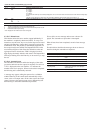
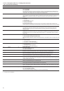
4.3.7 - Description of the Pressures menu
PRESSURES MENU [2]
ITEM FORMAT UNITS COMMENTS
0 nnnn kPa Discharge pressure, circuit A.
Relative pressure.
1 nnn kPa Suction pressure, circuit A.
Relative pressure.
2 [1] nnnn kPa Discharge pressure, circuit B.
Relative pressure.
3 [1] nnn kPa Suction pressure, circuit B.
Relative pressure.
1 This item is displayed in certain unit configurations only.
2 Access to this menu is read-only