


20
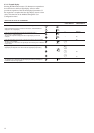
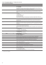
OUTPUTS STATUS & TESTS MENU [2] [3] continued
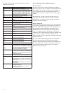
ITEM FORMAT UNITS
13 [1] b
1
b
2
b
3
b
4
tESt
14 [1] YES -
no -
tESt %
15 Auto tESt -
DESCRIPTION
Additional heating stage status.
b
1
= stage 1
b
2
= stage 2
b
3
= stage 3
b
4
= stage 4
In test mode the arrow keys successively display 0001, 0010, 0100 and 1000 to force the status of each electric heating stage
in turn.
This item is only displayed for heat pump units controlling additional electric heater stages. See section 5.12.
Used for local interface test only. Lights or flashes all LEDs and blocks, so as to check that they are working properly.
Automatic test. Selecting this item activates the automatic test function.
1 This item is displayed in certain unit configurations only.
2 Testing authorised only if the unit is in Local Off and all compressors are off.
3 Password needed only for testing.
“Test” Displayed in turn with the item value during tests.
4.3.10.3 - Manual tests
This function allows the user to test the outputs individually, if
the machine is completely shut down (LOFF). To carry out a
manual test use the arrow keys to access the output to be tested
and press the Enter key (longer than 2 seconds) to activate the
modification mode. The password is automatically requested, if it
has not previously been verified. The Outputs/Test LED on the
user interface begins to flash. Enter the desired test value and
again press Enter to start the test. 'TESt' is displayed on the 4-
digit display alternately with the value tested. The Outputs/Test
LED stops flashing. Press the Enter key or an arrow key to stop
the test.
4.3.10.4 - Automatic tests
The automatic test function verifies the integrity of the analo-
gue entries and activates the outputs in sequence. For each test
't XX' is displayed on the user interface. 'xx' indicates the
number of the test in progress. When a test has been completed,
the following test is automatically activated.
A message may appear, asking the operator for a validation
with the Enter key, if the control cannot automatically verify a
sensor value or an output status. If the value read or the output
status is incorrect, the operator must press a different key (not
the Enter key) to cancel the automatic test procedure.
If a test fails, an error message and an error code are dis-
played. The automatic test procedure is interrupted.
When all tests have been completed, an end-of-test message
appears.
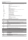
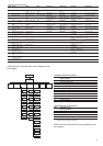
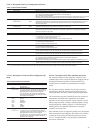
The table below describes the messages shown on the user
interface during the automatic test sequence.
TEXT DESCRIPTION
Thermistor test failed [XX] Test number XX of the thermistor has failed
Pressure test failed [XX] Test number XX of the pressure sensor has
failed
Output test failed [XX] Output test number XX has failed
Input test failed [XX] Input test number XX has failed
Press enter if test [XX] correct Request for the operator to validate test XX
OAT [value] press enter if Request for the operator to validate the
test [XX] correct outdoor air temperature value displayed.
Test number XX
Auto test completed Automatic test completed