


4
1 - SAFETY CONSIDERATIONS
1.1 - General
Installation, start-up and servicing of equipment can be
hazardous if certain factors particular to the installation are not
considered: operating pressures, presence of electrical
components and voltages and the installation site (elevated
plinths and built-up up structures). Only properly qualified
installation engineers and highly qualified installers and
technicians, fully trained for the product, are authorised to
install and start-up the equipment safely. During all servicing
operations all instructions and recommendations which appear
in the installation and service instructions for the product, as
well as on tags and labels fixed to the equipment and
components and accompanying parts supplied separately, must
be read, understood and followed.
• Apply all standard safety codes and practices.
• Wear safety glasses and gloves.
• Use the proper tools to move heavy objects. Move units
carefully and set them down gently.
1.2 - Avoid electrocution
Only personnel qualified in accordance with IEC (International
Electrotechnical Commission) recommendations may be
permitted access to electrical components. It is particularly
recommended that all sources of electricity to the unit be shut
off before any work is begun. Shut off the main power supply
at the main circuit breaker or isolator.
IMPORTANT: This equipment uses and emits
electromagnetic signals. Tests have shown that the equipment
conforms to all applicable codes with respect to
electromagnetic compatibility.
RISK OF ELECTROCUTION: Even when the main circuit
breaker or isolator is switched off, certain circuits may still
be energised, since they may be connected to a separate power
source.
RISK OF BURNS: Electrical currents cause components to
get hot either temporarily or permanently. Handle power
cable, electrical cables and conduits, terminal box covers and
motor frames with great care.
Fan start-up:
ATTENTION: In accordance with the operating conditions
the fans can be cleaned periodically. A fan can start at any
time, even if the unit has been shut down.
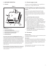
2 - GENERAL DESCRIPTION
2.1 - General
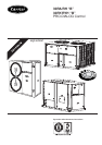
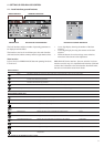
Pro-Dialog is a system for controlling single or dual-circuit
30RA/RY air-cooled liquid chillers or air-to-water 30RH/RYH
heat pumps. Pro-Dialog controls compressor start-up needed to
maintain the desired heat exchanger entering or leaving water
temperature. In cooling mode it controls the operation of the fans
to maintain the correct condensing pressure in each circuit. For
heat pump units it controls and optimises the defrost cycles of
each circuit in order to minimize the heating capacity
reduction. Safety devices are constantly monitored by Pro-
Dialog to ensure their safe operation. Pro-Dialog also gives
access to a Quick Test program covering all inputs and outputs.
All PRO-DIALOG controls can work in accordance with three
independent modes:
• Local mode: the machine is controlled by commands from
the user interface.
• Remote mode: the machine is controlled by remote
contacts (volt-free contacts).
• CCN mode: the machine is controlled by commands from
the Carrier Comfort Network (CCN). In this case, a data
communication cable is used to connect the unit to the
CCN communication bus.
The operating mode must be chosen with the Start/Stop button
described in section 4.2.1. When the PRO-DIALOG system
operates autonomously (Local or Remote mode) it retains all of
its own control capabilities but does not offer any of the
features of the CCN network.
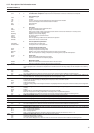
2.2 - Abbreviations used
In this manual, the refrigeration circuits are called circuit A and
circuit B. The compressors in circuit A are labelled A1, A2 and
A3. Those in circuit B are B1, B2 and B3.
The following abbreviations are used frequently:
CCN : Carrier Comfort Network
CCn : Operating type: CCN
LED : Light Emitting Diode
LOFF : Operating type: Local Off
L-On : Operating type: Local On mode
L-Sc : Operating type: Local On following a time schedule
MASt : Operating type: master unit (master/slave assembly)
rEM : Operating type: by remote contacts
SCT : Saturated Condensing Temperature
SIO : Sensor Bus (internal communication bus linking the
basic board to the slave boards)
SST : Saturated Suction Temperature
TXV : Thermal Expansion Valve