


35
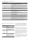
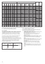
A
LARM
C
ODE
1
2
3
5
6
7
9
10
11
12
13
14
15
16
17
18
21
22
23
24
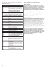
ALARM NAME
Compressor A1 failure
Compressor A2 failure
Compressor A3 failure
Compressor B1 failure
Compressor B2 failure
Compressor B3 failure
Heat exchanger leaving fluid
thermistor failure
Heat exchanger entering fluid
thermistor failure
CHWS fluid thermistor failure
(master/slave)
Defrost sensor fault, circuit A
Defrost sensor fault, circuit B
OAT sensor failure
Discharge pressure transducer
failure, Circuit A
Discharge pressure transducer
failure, Circuit B
Suction pressure transducer
failure, Circuit A
Suction pressure transducer
failure, Circuit B
CCN/clock board failure
Loss of communication with
slave board
Loss of communication with
compressor slave board
Loss of communication with PD-
4 x DO slave board
ALARM DESCRIPTION
Motor safety input has opened due to
compressor overtemperature protection.
As above
As above
As above
As above
As above
Thermistor outside range
As above
As above
As above
As above
As above
Voltage delivered by the sensor is incorrect
Value read by the sensor is outside range
Voltage delivered by the sensor is incorrect
Value read by the sensor is outside range
The clock board is no longer detected
Communication has been lost with the slave
board (circuit B control)
Communication has been lost with the
compressor A3 + B3 control board
Communication has been lost with the
electric heating stage control board
ACTION TAKEN BY
THE CONTROL
Compressor is shut
down
As above
As above
As above
As above
As above
Unit shut down
As above
As above
Circuit shut down, if unit
is in heating mode
As above
As above
Circuit A shut down
Circuit B shut down
Circuit A shut down
Circuit B shut down
Unit shut down
Circuit B shut down
Compressors A3 + B3
shut down
Electric heating stages
shut down
RESET TYPE
Manual
As above
As above
As above
As above
As above
Automatic, if temp. measured by sensor
returns to permitted range of values
As above
As above
As above
As above
As above
Automatic if the voltage delivered by the
sensor returns to normal
As above
As above
As above
Automatic if board is detected again
Automatic if communication is re-
established
As above
As above
PROBABLE CAUSE
Compressor overheat
As above
As above
As above
As above
As above
Faulty thermistor, wiring error or
disconnection
As above
As above
As above
As above
As above
Defective transducer, wiring fault
As above
As above
As above
Defective CCN/clock board
Bus wiring fault, wrong software in slave
board or defective slave board
As above
As above
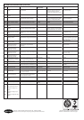
ALARM CODE DESCRIPTIONS
6 - DIAGNOSTICS - TROUBLESHOOTING
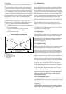
6.1 - General
The PRO-DIALOG control system has many fault tracing aid
functions. The local interface and its various menus give access
to all unit operating conditions. The test function makes it
possible to run a quick test of all devices on the unit. If an
operating fault is detected, an alarm is activated and an alarm
code is stored in the Alarm menu.
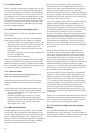
6.2 - Displaying alarms
The alarm LEDs on the summary interface (see section 4.1)
give a quick display of the status of each circuit and the unit as
a whole.
- A flashing LED shows that the circuit is operating but
there is an alarm.
- A steady LED shows that the circuit has been shut down
due to a fault.
The Alarm menu on the main interface displays up to 5 fault
codes that are active on the unit.
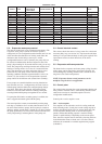
6.3 - Resetting alarms
When the cause of the alarm has been corrected the alarm can
be reset, depending on the type, either automatically on return
to normal, or manually when action has been taken on the unit.
Alarms can be reset even if the unit is running.
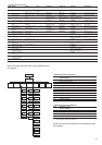
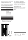
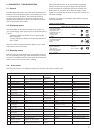
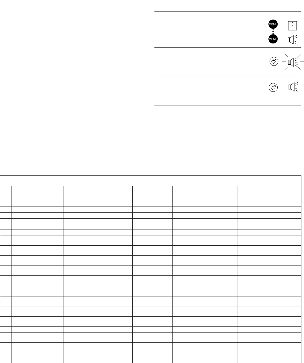
RESET OF ACTIVE ALARMS
OPERATION ITEM NUMBER ITEM VALUE PRESS MENU
2-DIGIT DISPLAY 4-DIGIT DISPLAY BUTTON LED
Hold down the MENU
button until the LED for
alarms lights. The 4-
digit display shows the
number of active
alarms (2 in this
example).
Press the Enter button
until "rESEt ALARrM" is
shown in the 4-digit
display.
Press the Enter button
again to validate the
reset. "Good" is
displayed for 2 seconds
then, "2 ALArM" and
then, "no ALArM".
0
0 2 ALArM
0 rESEt ALArM
0 Good
then, 2 AL
then, no ALArM
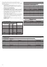
This means that an alarm can be reset without stopping the
machine. In the event of a power supply interrupt, the unit
restarts automatically without the need for an external com-
mand. However, any faults active when the supply is inter-
rupted are saved and may in certain cases prevent a circuit or a
unit from restarting.
A manual reset must be run from the main interface using the
following procedure:
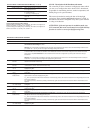
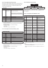
6.4 - Alarm codes
The following list gives a complete description of each alarm code and its possible cause.