


16
DESCRIPTION
The delay at start-up operates after the unit has been switched on. If the delay has not expired, the mode is
active. The delay is configured in the User Configuration 1 menu.
The second cooling/heating setpoint is active. See section 5.6.1
The third heating setpoint is active. See section 5.6.1
In this mode, the unit uses the reset function to adjust the leaving water temperature setpoint. See section 5.6.
If the unit is in auto mode, the heating/cooling changeover is automatic, based on the outdoor temperature. See
section 5.2.
In this mode, the demand at which the unit is authorised to operate is limited. See section 5.7.
Ramp loading is active. In this mode, the rate of water temperature drop or rise (heating mode) in °C/min is limited
to a preset value in order to prevent compressor overloading. Ramp function must be configured (see User
Configuration 1 menu). Ramp values can be modified (see Setpoint menu).
The water or air heat exchanger heater is active. See section 5.5.
The unit is fitted with two evaporator water pumps and reversal between pumps is in effect. See section 5.3.
The unit is stopped and the pump is started each day at 14.00 p.m. for two seconds. This function needs to be
configured in the User Configuration 1 menu. See section 5.3 & 4.3.11.3.
The night mode is active. Fan runs at low speed (if permitted by operating conditions) and unit capacity can be
limited. See section 5.8 & 4.3.11.3.
12 = circuit A & 13 = circuit B. Protection for evaporator low suction temperature circuit is active. In this mode,
circuit capacity is not authorised to rise and the circuit can be unloaded.
14 = circuit A & 15 = circuit B. The unit is in cooling or heating mode. The circuit is in high pressure protection
mode because the HP protection threshold has been exceeded. Circuit has been unloaded and the circuit
capacity is not authorised to rise.
16 = circuit A & 17 = circuit B. The unit is in heating mode, and the defrost sequence is active on the relevant
circuit.
The unit is in heating mode and compressor start is not authorised, as the entering water temperature is below
10°C.
19 = circuit A & 20 = circuit B. The unit is in heating protection mode and hot gas discharge protection is active. In
this mode, the circuit capacity cannot increase, and the circuit may be unloaded or go into defrost mode.
21 = circuit A & 22 = circuit B. The unit is in heating mode and low suction temperature protection is active. In this
mode, circuit capacity is not authorised to rise and the circuit can be unloaded or go into defrost mode.
The unit controls a boiler and this is operating. See section 5.13.
The unit controls additional electric heating stages, and these are operating. See section 5.12.
Unit is in control of a System Manager (FSM, CSM III or HSM).
Unit is connected to a secondary unit by a master slave link and the master/slave modes are active.
The unit is in heating mode, and compressor start-up is not permitted, when the outside air temperature is lower
than the value configured in item 12 of the User 1 configuration menu. See the relevant section.
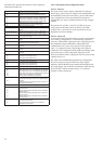
MODE # MODE NAME
1 Delay at start-up active
2 2nd cooling/heating setpoint active
3 3rd heating setpoint active
4 Setpoint reset active
5 Auto heating/cooling changeover
active
6 Demand limit active
7 Ramp loading active
8 Water or air heat exchanger
heater active
9 Evaporator pump reversal in effect
10 Evaporator pump periodic start
11 Night condensing mode
12, 13 Low suction temperature protection
14, 15 High pressure protection
16, 17 Defrost
18 Low water entering temperature
protection in heating mode
19, 20 Hot gas protection in heating mode
21, 22 Low suction temperature protection
in heating mode
23 Boiler active
24 Electric heating stages active
25 Unit in SM control
26 Master/slave link active
27 Low outside temperature protection
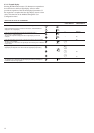
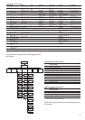
INFORMATION MENU (3) continued
ITEM FORMAT UNITS
14 ±nn.n °C
15 ±nn.n
Forc °C
16 ±nn.n °C
1 This item is masked when nil.
2 This item is displayed in certain unit configurations only.
3 Access to this menu is read-only except for item 10 that can be forced when the unit is in Local operating type.
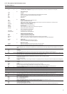
DESCRIPTION OF OPERATING MODES (ITEM 1 OF THE INFORMATION MENU)
DESCRIPTION
Active setpoint. This is the current cooling/heating setpoint: it refers to cooling setpoint 1 or cooling/heating setpoint 2. See section
5.6.1.
Control point. This is the setpoint used by the controller to adjust the temperature of the leaving or entering water (according to
configuration).
Control point = active setpoint + reset. See section 5.6
The value is displayed in turn with 'Forc' when the unit is in CCN control and if this variable if forced through CCN.
Controlled water temperature. Water temperature that the unit tries to maintain at the control point.