


19
4.3.10 - Description of the Outputs/Tests menu
4.3.10.1 - General
This menu displays the status of the controller outputs. More-
over, when the machine is fully stopped (LOFF) the outputs
can be activated for manual or automatic tests (the access to the
tests is password controlled).
4.3.10.2 - Menu description
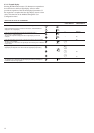
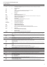
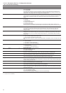
OUTPUTS STATUS & TESTS MENU [2] [3]
ITEM FORMAT UNITS
0b
1
b
2
b
3
tESt
FAIL
Good -
1 [1] b
1
b
2
b
3
tESt
FAIL
Good -
2 StoP
LOW
HIGH
tESt -
3 [1] StoP
LOW
HIGH
tESt -
4 [1] b
1
b
2
-
5 [1] On
OFF
tESt
FAIL
Good
Forc -
6 [1] On
OFF
tESt
FAIL
Good
Forc -
7On
OFF
tESt -
8b
1
b
2
tESt -
9 [1] On
OFF
tESt -
10 [1] nnn
tESt %
11 [1] nnn
tESt %
12 [1] b
1
b
2
tESt
DESCRIPTION
Circuit A compressors, command status
b
1
= compressor A1
b
2
= compressor A2
b
3
= compressor A3
In test mode, the Arrow buttons display 001, 010 and 100 in succession, so as to force the status of the compressor outputs
in turn. During the test phase, power to the compressor is switched on for 10 seconds only. It is then not possible to restart the
compressor for a further 30 seconds. When the test is completed the following is displayed:
- Fail: displayed if the test has failed because the compressor was not started or run in reverse rotation.
- Good: displayed if test was successful
Circuit B compressor, dual-circuit units only
b
1
= compressor B1
b
2
= compressor B2
b
3
= compressor B3
In test mode... as above
Two-speed fan status, circuit A
Stop = fan is stopped
Low = fan is in low speed
High = fan is in high speed
Two-speed fan status, circuit B
Stop = fan is stopped
Low = fan is in low speed
High = fan is in high speed
Single-speed fan status
b
1
= fan A2
b
2
= fan B2
Only for dual-circuit units
Evaporator water pump #1 command status. Not displayed if the unit does not control a pump.
On: pump is running
Stop: pump is stopped
Forc: this item is displayed only when the unit is stopped locally (LOFF). selecting this item authorises turning on the
pump with no delay and for an unlimited length of time. The pump will remain on until any button of the user interface is
pressed: it is then immediately stopped. If the unit is in CCN control, then the pump status is displayed in turn with "Forc"
if the pump status if forced through CCN.
During the test phase, power to the pump is switched on for 10 seconds only. When the test is completed the following is
displayed:
- Fail: displayed if the test has failed because the pump was not started
- Good: displayed if the test was successful
Evaporator water pump #2 command status. Not displayed if the unit does not control a secondary pump.
On: pump is running
Stop: pump is stopped
Forc: this item is displayed only when the unit is stopped locally (LOFF). selecting this item authorises turning on the
pump with no delay and for an unlimited length of time. The pump will remain on until any button of the user interface is
pressed: it is then immediately stopped. If the unit is in CCN control, then the pump status is displayed in turn with "Forc"
if the pump status if forced through CCN.
During the test phase, ...as above
Water or air heat exchanger heater command status
See sections 5.5 and 5.11
Alarm output command status
b
1
= alarm circuit A
b
2
= alarm circuit B
In test mode, the Arrow buttons display 01 and 10 in succession, so as to force each alarm output status in turn.
Boiler command status. Displayed if the unit controls a boiler. See section 5.13.
Variable fan speed, circuit A. Displayed if the unit controls a variable-speed fan.
Variable fan speed, circuit B. Dual-circuits only and if the unit controls a variable-speed fan.
4-way reversing cycle valve status. In test mode, the arrow keys successively display 01 and 10, in order to authorise the
test for each valve in turn.
b
1
= valve circuit A
b
2
= valve circuit B
This item is only displayed for heat pump units.