


22
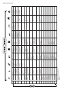
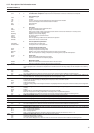
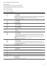
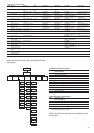
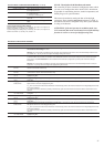
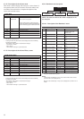
The table below describes the faults that can be displayed
during the automatic test.
TEST FAULT
1
2
3
4
5
6
7
8
9
10
11, 12, 13; 14, 15
16, 17, 18, 19, 20
21
22, 23; 24, 25, 26
27
28
29
30
31
32
33
34
35
36
37
38
39
40
41
42
43
44
45
46
47
48
49
50
51
52
53
DESCRIPTION
Outdoor air thermistor outside range
Outdoor air value read not validated by operator
Low pressure transducer, circuit A, outside range
High pressure transducer, circuit A, outside range
Low pressure transducer, circuit B, outside range
High pressure transducer, circuit B, outside range
Defrost thermistor, circuit A, outside range
Defrost thermistor, circuit B, outside range
Water flow switch not open
Primary pump not started or water flow switch not
closed
Water entering temperature sensor outside range
Water leaving temperature sensor outside range
Temperature difference between entering and leaving
water sensors too high
Water system leaving temperature sensor outside
range
Temperature difference between the system entering
and leaving water sensors too high
Water flow switch not closed or primary pump not
stopped
Secondary pump not started or water flow switch not
closed
Water flow switch not closed or secondary pump not
stopped
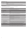
Command fault; compressor A1
Command fault; compressor A2
Command fault; compressor A3
Command fault, 4-way reversing valve, circuit A
Command fault; compressor B1
Command fault; compressor B2
Command fault; compressor B3
Command fault, 4-way reversing valve, circuit B
Low-speed test, fan A1 not validated by the operator
High-speed test, fan A1 not validated by the operator
Low-speed test, fan B1 not validated by the operator
High-speed test, fan B1 not validated by the operator
Test fan A2 not validated by the operator
Test fan B2 not validated by the operator
Water heat exchanger heater and air heat exchanger
condensate heater test, circuit A not validated by the
operator
Air heat exchanger condensate heater, circuit B, not
validated by the operator
Boiler activation test not validated by the operator
Electric heating stage 1 activation test not validated
by the operator
Electric heating stage 2 activation test not validated
by the operator
Electric heating stage 3 activation test not validated
by the operator
Electric heating stage 4 activation test not validated
by the operator
Alarm relay output activation test, circuit A not
validated by the operator
Alarm relay output activation test, circuit B not
validated by the operator
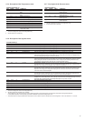
4.3.11- Description of the configuration menu
4.3.11.1- General
This menu can be used to display and modify all configura-
tions: Factory, Service and User. Only the User Configuration can
be modified by the end-user. The Factory, Service and master/
slave configurations are not described in this document. A
configuration can only be modified if the unit is fully stopped
(LOFF).
The menus User 1 [USEr 1] and User 2 [USEr 2] are pass-
word-protected. The other menus are directly accessible,
except if item 11 of the User 2 menu (password for all con-
figurations) has been validated.
4.3.11.2 - Password
A password must be entered in order to access the test function
or to modify a configuration. It is automatically requested, if
necessary: 'EntEr PASS' is displayed on the 4-digit display and
the configuration menu LED flashes, indicating that the
modification mode is active. Press the arrow keys until the
value '11' is displayed on the 4-digit display. Press Enter to
validate this. The configuration menu LED stops flashing. If the
password is correct, 'Good' is displayed. If the password is
incorrect, 'PASS incorrEct' is displayed. The User password has
a default value of 11.
This value can be modified through the Service configuration.
The password can be entered if the unit is fully stopped,
otherwise 'ACCES dEniEd' (access denied) will be displayed on
the 4-digit display. The controller automatically deactivates the
password after 5 minutes without activity (i.e. no buttons
pressed) or after powering up.