


15
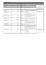
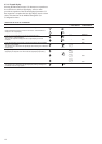
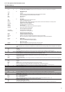
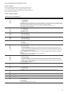
INFORMATION MENU (3)
ITEM FORMAT UNITS
0
±nn.n °C
LOFF -
L-On -
L-Sc -
CCn -
rEM -
MASt -
OFF -
rEADY -
dELAY -
StOPPing -
running -
triPout -
OvErridE -
dEFrOSt -
OCCUPIEd -
UNOCCUPIEd -
COOL -
HEAT -
StAndbY -
BotH -
ALArM -
ALErt -
MAStEr -
SLAvE -
1 [1] nn
-
2 [2] -
occu
unoc
Forc
3 nn.n minutes
4 [2] -
HEAt -
COOL -
Auto -
5 [2]
HEAt -
COOL -
StbY -
both -
Forc -
6 nnn %
7 nnn %
8 [2] nnn %
9 [2] nnn %
10 nnn
Forc %
11 [2] nnn %
12 [2] -
SP-1
SP-2
SP-3
AUtO
13 [2] -
occu
unoc
Forc
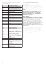
4.3.5 - Description of the Information menu
DESCRIPTION
Automatic display mode. It cycles through the following displays:
1: Controlled water temperature: temperature of the water that the unit tries to maintain at the control point.
2: Unit operating type
Local Off
Local On
Local On - based on unit clock. Displayed if the CCN/clock board is installed.
CCN Control. Displayed if the CCN/clock board is installed.
Remote Control
Master unit
3: Unit status
Off: Unit is stopped and not authorised to start.
Ready: Unit is authorised to start
Delay: Unit is in delay at start-up. This delay is active after the unit has been switched on. The delay can be
configured in the User Configuration menu.
Stopping: Unit is currently stopping.
On: Unit is running or authorised to start.
Fault shutdown.
Limit: The operating conditions do not allow total unit operation.
Defrost: One circuit is in defrost mode.
4. Unit occupied/unoccupied status
Occupied: Unit in occupied mode
Unoccupied: Unit in unoccupied mode
5. Heating/cooling operating mode
Cooling: Unit operates in cooling mode
Heating: Unit operates in heating mode
Standby: Unit is in auto cooling/heating changeover mode, and is in standby
Both: The unit operates in cooling (compressors) and heating (boiler). Only with HSM operation.
6: Alarm mode
Alarm: Unit is totally stopped because of failure.
Alert: Unit is in failure but not completely stopped.
7: Master/Slave status
Master: The master/slave control is active and the unit is the master
Slave: The master/slave control is active and the unit is the slave
Active mode codes. Each active mode is displayed in turn. This Item is masked when nil. Pressing the enter button when a mode
code is displayed causes a character text expansion to be scrolled accross the four-digit display. See the description in the following
table
This item indicates the current unit occupied/unoccupied mode. Displayed if the CCN/clock board is installed.
Occupied
Unoccupied
The value is displayed in turn with 'Forc' when the unit is in CCN control and if this variable if forced through CCN.
Start-up delay. This item indicates the minutes left before the unit can be started. This delay at start-up is always active after the unit
has been switched on. The delay can be configured in the User Configuration 1 menu.
Heating/cooling on selection: This item is accessible in read/write, if the unit is in local control mode. It is only displayed, if the unit is
in LOFF, L-On or L-Sc operating type. Displayed for heat pumps or if the unit controls a boiler.
Heating mode selection
Cooling mode selection
Automatic heating/cooling mode changeover selection. Only displayed if the auto changeover function is selected (User Configuration
1 menu).
Heating/cooling mode. This item indicates whether the unit is in cooling or heating. Displayed if the unit controls a boiler.
Heating
Cooling
Standby: Unit is in auto cooling/heating changeover mode, and is in standby.
Both: The unit operates in cooling (compressors) and heating (boiler). Only with HSM operation.
The value is displayed in turn with 'Forc' when the unit is in CCN control and if this variable if forced through CCN.
Total active capacity of unit. It is the percentage of compressor capacity used by the unit.
Total active capacity of circuit A. It is the percentage of compressor capacity used by on circuit A..
Total active capacity of circuit B. It is the percentage of compressor capacity used by on circuit B. Dual-circuit units only.
Active electric heating stages. Only displayed for heat pumps and if the unit controls additional electric heating stages.
Present demand limit. This is the authorised operating capacity of the unit. See section 5.7.
The value is displayed in turn with 'Forc' when the unit is in CCN control and if this variable if forced through CCN.
Present lag chiller demand limit. Displayed when the master/slave control is selected.
Setpoint select in local mode. This point is read/write accessible. Displayed only when the unit is LOFF, L-On or L-Sc operating type.
SP-1 = cooling/heating setpoint 1
SP-2 = cooling/heating setpoint 2
SP-3 = heating setpoint 3
AUtO = active setpoint depends on schedule 2 (setpoint selection schedule). See section 5.6.1 & 4.3.11.6.
Setpoint occupied mode. Displayed if the CCN/clock board is installed.
Occupied: cooling setpoint 1 is active
Unoccupied: cooling setpoint 2 is active
The value shall be displayed in turn with 'Forc' when the unit is in CCN control and if this variable if forced through CCN.