


9
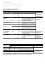
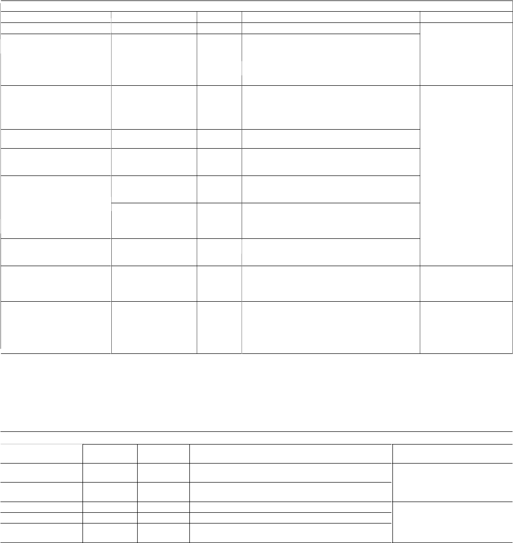
AVAILABLE TERMINALS
DESCRIPTION
Alarm relay output, circuit A
Alarm relay output, circuit B
User safety loop and chilled water
pump interlock
Remote start/stop
Remote cooling setpoint selection
Remote heating/cooling control
or
remote heat reclaim control
Demand limit command
0-10 V d.c. setpoint reset or
demand limit entry
Connection to CCN
CONNECTOR/CHANNEL
J3 / CH24
J3 / CH25
J4 / CH15a
J4 / CH11
J4 / CH12
J4 / CH13
J4 / CH13
J4 / CH14
J8 / CH10
J12
TERMINAL
30A - 31A
30B - 31B
34 - 35
32 - 33
65 - 66
63 - 64
63 - 64
73 - 74
71 - 72
1 - 2 - 3
DESCRIPTION
Indicates alarms in circuit A
Indicates alarms in circuit B
This contact is mounted in series with the water flow
control contact. It can be used for any user safety loop
that requires that the unit is shut down, if it is open. The
chilled water pump operation auxiliary contact is
connected between these two terminals.
The remote start/stop command is only used if the unit is
under remote operation control (rEM). See section 4.2.1.
The remote cooling setpoint selection command is only
used if the unit is under remote operation control (rEM).
See section 4.2.1.
The remote heating/cooling control command is only used
if the unit is under remote operation control (rEM). See
section 4.2.1.
The command allows selection of the second condensing
setpoint or of the heat reclaim mode. It is only used if the
unit is under remote operation control (rEM). See section
4.2.1.
This contact permits activating the unit demand limit
function. See section 5.8. This contact is active, whatever
the operating type.
This 0-10 V d.c. input is used for setpoint reset or unit
demand limit. It is active, whatever the unit operating type.
This 0-10 V signal can be supplied by a user command or
a 0-10 V temperature sensor.
A RS-485 bus is used for connection to the CCN.
The CCN connector is located on the CCN/clock board
(inserted on the PD4 Basic Board)
- Pin 1: signal +
- Pin 2: ground
- Pin 3: signal -
REMARKS
Volt-free contacts 24 V a.c. 48
V d.c. max, 20 V a.c. or V
d.c., 3 A max, 80 mA min,
external power supply.
Connector: 6 pin WAGO
231-306/026000 pitch 5.08.
24 V a.c., 20 mA
Connector: 10 pin WAGO
734-110, pitch 3.5
Connector: 2 pin WAGO 231-
302/026000 pitch 5.08
Use of a shielded cable (max.
length: 1000 m)
Shielding: braiding on 95% -
100% of the cable surface.
Shielding connection at the
two cable ends.
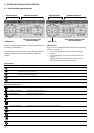
CONNECTION BLOCK
Description
Condenser water flow
switch input
Evaporator 1 and 2 pump
operation input
Evaporator 1 control
Evaporator 2 control
Condenser pump control
Connector/
channel
J5/CH17
J5/CH18
J2/CH19
J2/CH20
J2/CH21
Terminal Description
This contact is used to detect lack of condenser water flow and
shuts down the unit.
This contact is used to detect an evaporator pump operation
fault and switches over to the other evaporator pump*.
This contact permits control of evaporator 1 pump by the unit*.
This contact permits control of evaporator 2 pump by the unit*.
This contact permits control of condenser pump by the unit*.
Legend
* Associated functions, if selected: automatic changeover, pump 1 and 2; manual or CCN selection; periodical; by default.
Remarks
24 V a.c - 20mA
24 V a.c. internal supply.
Max. consumption
- each output: 20 VA/10W
- for all 3: 40 VA/20 W if all are used
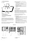
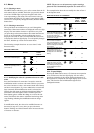
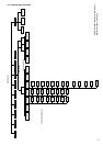
3.4 - User connections
The connections below are available at the customer’s terminal
block. Some of them can only be used in special operating
modes. For further details see the sections that describe the
functions (section 5) and the configurations (section 4.2.1).
NOTE: The bridge between terminals 32, 63 and 65 on the
customer’s terminal block must not be removed.