


32
6 - DIAGNOSTICS - TROUBLESHOOTING
6.1 - General
The PRO-DIALOG Plus control system has many fault tracing
aid functions. The local interface and its various menus give
access to all unit operating conditions. The test function makes
it possible to run a quick test of all devices on the unit. If an
operating fault is detected, an alarm is activated and an alarm
code is stored in the Alarm menu.
6.2 - Displaying alarms
The alarm LEDs on the summary interface (see section 4.1)
give a quick display of the status of each circuit and the unit as
a whole.
• A flashing LED shows that the circuit is operating but
there is an alarm.
• A steady LED shows that the circuit has been shut down
due to a fault.
The Alarm menu on the main interface displays up to 5 fault
codes that are active on the unit.
6.3 - Resetting alarms
When the cause of the alarm has been corrected the alarm can
be reset, depending on the type, either automatically on return
to normal, or manually when action has been taken on the unit.
Alarms can be reset even if the unit is running.
This means that an alarm can be reset without stopping the
machine. In the event of a power supply interrupt, the unit
restarts automatically without the need for an external com-
mand. However, any faults active when the supply is inter-
rupted are saved and may in certain cases prevent a circuit or a
unit from restarting.
A manual reset must be run from the main interface using the
following procedure:
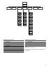
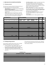
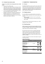
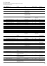
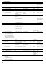
RESET OF ACTIVE ALARMS
OPERATION ITEM NUMBER ITEM VALUE PRESS MENU
2-DIGIT DISPLAY 4-DIGIT DISPLAY BUTTON LED
Hold down the MENU
button until the LED 0
for alarms lights. The
4-digit display shows 0 2 ALArM
the number of active
alarms (2 in this
example).
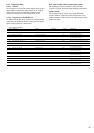
Press the Enter button 0 rESEt ALArM
until "rESEt ALARrM"
is shown in the 4-digit
display.
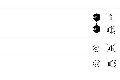
Press the Enter button 0 Good
again to validate the then, 2 AL
reset. "Good" is dis- then, no ALArM
played for 2 seconds
then, "2 ALArM" and
then, "no ALArM".
5.21 - Optional heat reclaim module
Change-over procedure from cooling mode to heat reclaim
mode:
• Start-up of the condenser pump
• Verification of the condenser flow switch control contact.
If this remains open after one minute of condenser pump
operation, the circuit remains in cooling mode and alarm
79 for circuit A (alarm 80 for circuit B) will be activated.
• As soon as the saturated condensing temperature reaches
30°C, the pumpdown sequence is activated.
• Pumpdown: closing of the cooling mode coil shutoff valve.
Opening of the drain valve, closing of the EXV valve.
• When the pumpdown pressure reaches the end of the
pumpdown threshold, the pumpdown valve is closed and
the heat reclaim function is effective.