


19
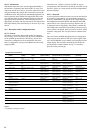
OUTPUTS STATUS 2 AND TESTS MENU [2] [3] - cont.
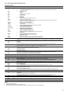
ITEM FORMAT UNITS
4 [1] tESt -
-
-
5 tESt
-
-
6 tESt %
7 tESt %
8 [1] tESt %
9 [1] tESt %
10 On -
Stop -
tESt -
FAIL -
Good -
Forc -
11 On -
OFF -
tESt -
FAIL -
Good -
Forc -
12 On -
OFF -
tESt
FAIL
Good
Forc
-
13[1] nn
-
-
14[1] tESt %
15[1]
-
-
-
-
16 YES
no
tESt
Legend
1 This item is displayed in certain unit configurations only
2 A test is only possible if the units are in local off mode and if all compressors have stopped
3 The password is only valid for the test. 'Test' is displayed during the test, alternating with the item number
DESCRIPTION
Fan contactor status/test, circuit B
b1 = fan contactor assembly 1
b2 = fan contactor assembly 2
b3 = fan contactor assembly 3
b4 = fan contactor assembly 4
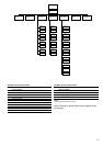
This item permits display of the fan stages. It also permits independent testing. In test mode the direction arrows permit
successive display of 0001, 0010, 0100 and 1000, so as to in turn force authorisation of each output.
Alarm command status/test
b1 = alarm circuit A
b2 = alarm circuit B
In test mode the direction arrows permit successive display of 01 and 10, so as to in turn force authorisation of each alarm
output.
EXV position, circuit A
In the test mode the direction arrows permit forcing the valve to its fully open position.
EXV position, circuit B
In the test mode the direction arrows permit forcing the valve to its fully open position.
Variable speed fan, circuit A or condenser water valve position in %
Variable speed fan, circuit B or condenser water valve position in %
Evaporator water pump No. 1 command status. Not displayed if unit does not control a pump.
On: the pump operates
Stop: the pump has stopped
Forc: This item is only displayed if the unit is in local off mode (LOFF). Selecting this item permits energising the pump
without delay and for an unlimited period. The pump continues to operate, until any key on the user interface is pressed: it is
then immediately switched off. If the unit is in CCN control mode, the pump status is displayed alternately with 'Forc' if its
status is forced by CCN.
During the test phase, pump supply is energised for 10 seconds only. When the test has finished, the following display
appears:
- Fail: displayed if the test has failed, because the pump is not started
- Good: displayed if the test succeeds
Evaporator water pump No. 2 command status. Not displayed if unit does not control a pump.
On: the pump operates
Stop: the pump has stopped
Forc: This item is only displayed if the unit is in local off mode (LOFF). Selecting this item permits energising the pump
without delay and for an unlimited period. The pump continues to operate, until any key on the user interface is pressed: it is
then immediately switched off. If the unit is in CCN control mode, the pump status is displayed alternately with 'Forc' if its
status is forced by CCN.
During the test phase, pump supply is energised for 10 seconds only. When the test has finished, the following display
appears:
- Fail: displayed if the test has failed, because the pump is not started
- Good: displayed if the test succeeds
Condenser pump status/test
On: the pump operates
Stop: the pump has stopped
Forc: This item is only displayed if the unit is in local off mode (LOFF). Selecting this item permits energising the pump
without delay and for an unlimited period. The pump continues to operate, until any key on the user interface is pressed: it is
then immediately switched off. If the unit is in CCN control mode, the pump status is displayed alternately with 'Forc' if its
status is forced by CCN.
During the test phase, pump supply is energised for 10 seconds only. When the test has finished, the following display
appears:
- Fail: displayed if the test has failed, because the pump is not started
- Good: displayed if the test succeeds
Evaporator heater and heat reclaim condenser status
b1 = evaporator heater
b2 = heat reclaim condenser heater
Condenser water valve position in heat reclaim mode
Solenoid valve status/test, heat reclaim function
b1 = heat reclaim coil shutoff solenoid valve, circuit A
b2 = heat reclaim coil drain solenoid valve, circuit A
b3 = heat reclaim coil shutoff solenoid valve, circuit B
b4 = heat reclaim coil drain solenoid valve, circuit B
In test mode the direction arrows permit successive display of 0001, 0010, 0100 and 1000, so as to in turn force authorisation
of each output.
Used only for local interface
Cause all diodes and blocks to light up or flash, to verify that they are operating correctly