


7
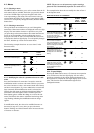
3.2.7 - Light emitting diodes on boards
All boards continuously check and indicate the proper
operation of their electronic circuits. A light emitting diode
(LED) lights on each board when it is operating properly.
Red LED
• The MAIN red LED flashes at about 2 second intervals to
show that the module is working properly.
• Irregular flashing or no flashing is a sign of a defective
board.
Green LED
(item SIO on the board)
• This LED flashes continuously to show that the board is
communicating correctly over its internal bus.
• If this LED is not flashing, check the wiring of the SIO
bus and the address of the board (slave board only). If the
basic board is not linked to any slave boards, this LED
should not flash.
• If all slave boards indicate a communication fault, check
the SIO bus connection on the basic board. If this
connection is correct and the fault persists, replace the
basic board.
Orange LED - CCN/clock board
• This LED flashes to show that the basic board is commu-
nicating via the CCN bus.
3.3 - The controls
3.3.1 - Electronic expansion valve (EXV)
The EXV is used to adjust the refrigerant flow to changes in
the operating conditions of the machine. For this purpose, a
series of calibrated orifices are machined into the wall of the
refrigerant inlet port. As the refrigerant passes through these
orifices, it expands and becomes a bi-phase mixture (liquid and
gas).
To adjust the refrigerant flow to changes in operating conditions,
a piston moves constantly up or down to vary the cross-section
of the refrigerant path. This piston is driven by an electronically
controlled linear stepper motor. The high degree of accuracy
with which the piston is positioned ensures that the flow of
refrigerant is precisely controlled.
NOTE: The external connector of the EXV must be cleaned
and coated with silicone grease (Part No. 397 EE) to keep out
condensation and prevent corrosion.
3.3.2 - The head pressure controls
The controller can deal with the following:
• in the case of air-cooled units, for each circuit, fan stages
together with, if necessary, a variable speed fan (controlled
by an optional 4xAI-2xAO board)
• in the case of water-cooled units, a water valve. This valve
is controlled by an optional 4xAI-2xAO board which can
deliver a 0-10 V d.c. or 4-20 mA signal, depending on the
configuration.
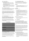
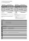
3.2.3 - The user interface
The user interface is in two parts:
• The main interface: This gives access to all of the
control parameters for the unit. It consists of a 2-digit
primary display block and a secondary 4-digit display
block with 10 LEDs and 5 buttons.
• The summary interface: This gives quick access to just
the main control parameters for the unit. It comprises 12
buttons and 16 LEDs, and includes a schematic diagram
of the unit.
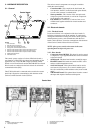
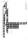
3.2.4 - Connections between boards
The basic board and slave boards communicate with each other
over an internal three-wire RS485 communication bus (SIO
bus). These three wires link all the boards in parallel.
Terminals 1, 2 and 3 on connector J9 (A, B, C are connected
internally) of the basic board are connected to terminals 1, 2
and 3 of terminal J9 of the NRCP-BASE board, terminal J4 of
the PD4-EXV board respectively, except for terminal J3 of the
4xDO and 4xAI-2xAO boards where terminals 2 and 3 are
reversed.
Incorrect connection will render the system inoperative.
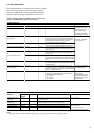
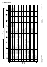
3.2.5 - Slave board addresses
Every slave board (except the NRCP-BASE board) has a
unique address controlled by 8 DIP switches. The switch is
disabled when it is in the open position (OPEN or OFF). On
RCPM boards SIO address switch is labelled 'ADDR'.
NOTE: Any incorrect address will prevent the unit from
starting. Turn off the power before amending the address of
any auxiliary board.
Board addresses
Board Address switch
87654321
PD4-EXV 0 0 011101
4xDO Fan board # 1 0 0 100111
4xDO Fan board # 2 0 0 101011
4xAI-2xAO board # 1 0 0 101111
4xAI-2xAO board # 2 0 1 111000
RCPM # 1 (compressor A1) 1 1 010100
RCPM # 2 (compressor A2) 1 1 011111
RCPM # 2 (compressor A3) 1 1 011001
RCPM # 2 (compressor A4) 1 1 100100
RCPM # 3 (compressor B1) 1 1 101010
RCPM # 4 (compressor B2) 1 1 110101
RCPM # 4 (compressor B3) 1 1 101111
RCPM # 4 (compressor B4) 1 1 110010
3.2.6 - Power supply to the boards
All boards are supplied by a 24 V source, referred to earth. In the
event of a power supply interrupt, the unit restarts automatically
without the need for an external command. However, any faults
active when the supply is interrupted are saved and may in
certain cases prevent a circuit or unit from restarting.
NOTE: When connecting the power supply for the boards,
maintain polarity.