


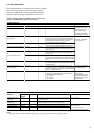

6
3 - HARDWARE DESCRIPTION
3.1 - General
Control board
The various control components are arranged in modules
within the control cabinet:
• Control module: This comprises the basic board, the
user interface, the EXV control board and option boards,
as well as the customer’s terminal block.
• Start-up module: This consists of the start-up boards,
compressor protection boards, as well as the compressor
circuit breakers and contactors.
• Fan module (air-cooled unit): Consists of one or two
4xDO boards together with the fan circuit breakers and
contactors.
3.2 - Electronic boards
3.2.1 - The basic board
It can be used alone or in conjunction with slave boards. It
holds the program that controls the machine. It continuously
manages the information coming in from the various pressure
and temperature sensors, and communicates with the slave
boards via the SIO bus. It can also communicate with elements
of the Carrier Comfort Network via the CCN bus.
NOTE: After a power cut the unit restarts in the same
operating mode as before the power cut.
3.2.2 - Slave boards
• Compressor board RCPM: This board is used to control
a compressor. Up to eight RCPM boards can be connected
to the basic board.
• 4xDO board: This board can be used to control fan stages.
• PD4-EXV board: This board can control two EXV valves
and two suction temperature sensors.
• 4xAI-2xAO board: This optional board can be used to
read sensors (oil pressure), or to control variable speed
fans (air-cooled units) or the condenser valve (water-cooled
units).
• NRCP-BASE board: This optional board is used to control
the inputs and outputs of the heat reclaim option.
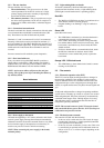
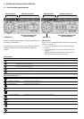
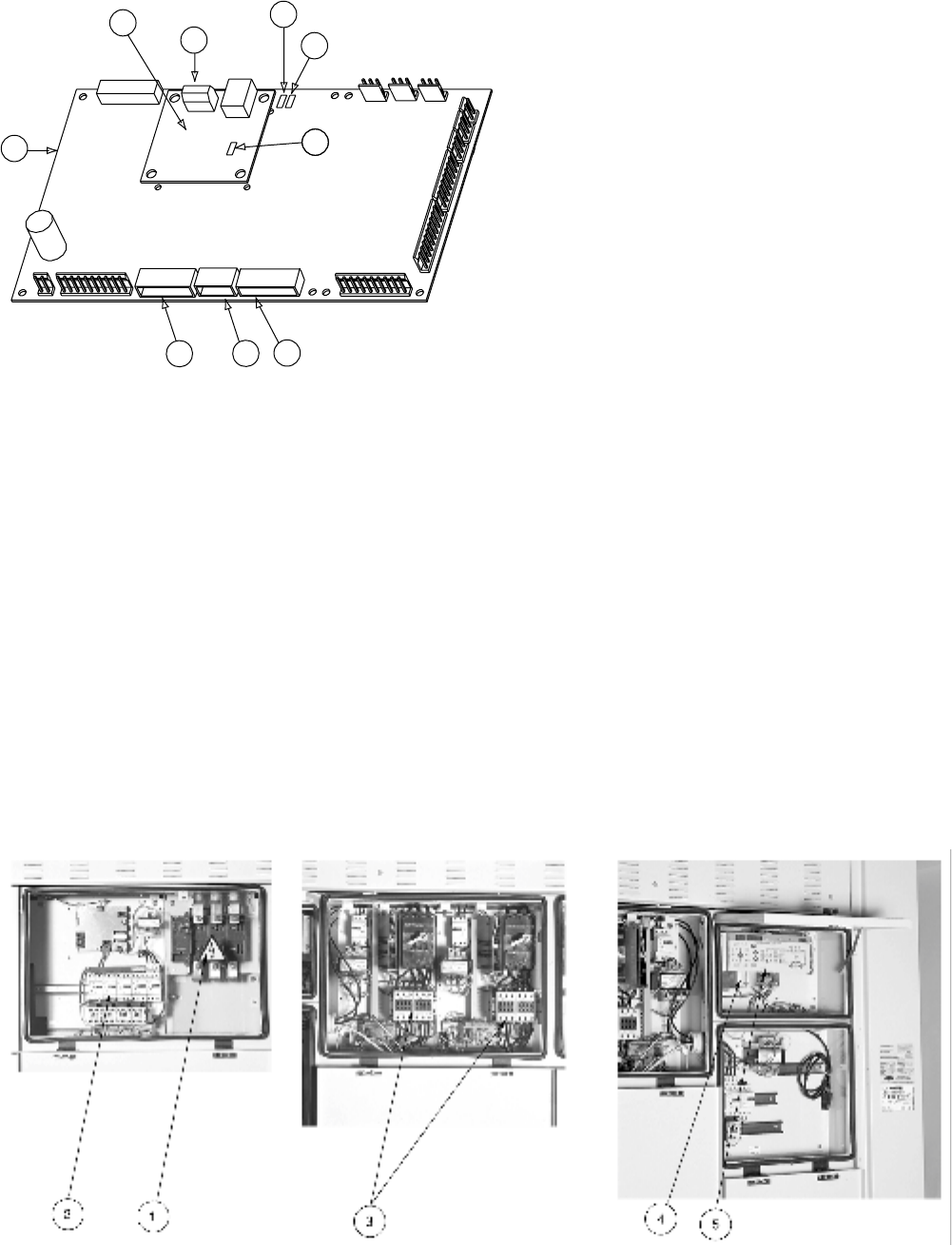
Legend
1 CCN connector
2 Red LED, status of the board
3 Green LED, communication bus SIO
4 Orange LED, communication bus CCN
5 Remote master board customer control connection contacts
6 Remote master board customer control connection signal
7 Remote master board customer report connection contacts
8 Master PD4 basic board
9 CCN/clock board
The control system consists of at least a PD4 basic board, a
user interface, a PD4-EXV slave board and, depending on the
application, one or more RCPM compressor boards, 4xDO
boards or 4xAI-2xAO boards and an NRCP-BASE slave board.
Slave boards are connected to the basic board via an internal
communication bus (SIO).
The CCN/clock board is connected and screwed to the master
basic board. It permits communication with elements of the
Carrier Comfort Network via the CCN bus.
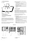
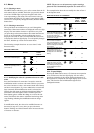
Control box
3 Compressor start-up module
4 Control system
5 User interface
Legend
1 Power supply disconnect switch
2 Fan start-up module
1
2
8
9
5
4
6
7
3