


16
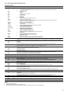
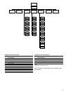
DESCRIPTION OF OPERATING MODES (ITEM 1 OF THE INFORMATION MENU)
MODE #MODE NAME
7 Delay at start-up active
8 2nd cooling setpoint active
9 Setpoint reset active
10 Demand limit active
11 Ramp loading active
12 Low entering water temperature
protection in heating mode
13,14 Low suction temperature protection
15,16 Low discharge superheat protection
17,18 High pressure protection
19,20 Not used
21 Heat reclaim active
22 Evaporator heater active
23 Evaporator pump reversal active
24 Periodic evaporator pump start-up
25 Low night-time capacity
26 Unit under SM control
27 Master/slave link active
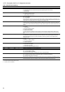
DESCRIPTION
The delay at start-up operates after the unit has been switched on. If the delay has not expired, the mode is active.
The delay is configured in the User1 configuration menu.
The second cooling setpoint is active. See section 5.7.1
In this mode, the unit uses the reset function to adjust the leaving or entering water temperature setpoint. See
section 5.7.2.
In this mode, the capacity at which the unit is allowed to operate is limited. See section 5.8.
Ramp loading is active. In this mode, the controlled high or low water temperature value (in °C/min) in heating mode
is limited to a preset value in order to prevent compressor overload. The ramp function must be configured (see
User1 configuration menu). The ramp values can be modified (see setpoint menu).
The unit is in heating mode and the temperature of the evaporator leaving water is lower than the lesser of the two
cooling setpoints. A capacity stage is removed. This mode only applies to heat pumps.
13 = circuit A & 14 = circuit B. Protection for evaporator suction low temperature circuit is active. In this mode, circuit
capacity is not authorised to rise if the unit is in cooling mode, and saturated suction temperature in the circuit is
lower by more than 13°C at the leaving chilled water and lower than the frost protection threshold.
15 = circuit A & 16 = circuit B.
In this mode the circuit capacity is shut down by pumpout and not allowed to restart, when the low superheat alarm
conditions are satisfied. During the shutdown/start-up sequence, mode 15 or 16 is active. See descriptions for
alarms 48 and 49.
17 = circuit A & 18 = circuit B. The circuit is in high pressure protection mode because the HP protection threshold
has been exceeded. The circuit capacity is not authorised to rise and any slave compressor can be stopped in order
to prevent a high pressure break.
Circuit A or circuit B operates in heat reclaim mode and not in standard cooling mode (pumpdown phase is
activated).
Mode active if risk of frost exists.
Two evaporator water pumps installed on the unit and pump reversal is active. See section 5.3
The unit is shut down and is started every day at 14:00 hours for 2 seconds. This function must be configured in the
User1 menu. See sections 5.3 and 4.5.7.3.
Unit capacity is limited. The period when this mode starts, as well as the limited capacity in night-time mode are
controlled in Client1 menu.
Unit is under control of a System Manager (FSM or CSM III).
Unit is connected to a secondary unit by a master slave link and either:
- the unit is configured as a master and this master is operating, or
- the unit is configured as a slave and this slave is operating.
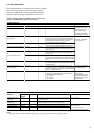
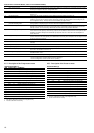
4.5.2 - Description of the Temperatures menu
TEMPERATURES MENU [2]
ITEM FORMAT UNITS COMMENTS
0 ±nn.n °C Evaporator entering water temperature
1 ±nn.n °C Evaporator leaving water temperature
2[1] ±nn.n °C Condenser entering water temperature
3[1] ±nn.n °C Condenser leaving water temperature
4[1] ±nn.n °C Reclaim condenser entering water temperature
5[1] ±nn.n °C Reclaim condenser leaving water temperature
6 ±nn.n °C Saturated discharge temperature circuit A
7 ±nn.n °C Saturated suction temperature circuit A
8 ±nn.n °C Suction temperature compressor A1
9 ±nn.n °C Superheat circuit A
10[1] ±nn.n °C Saturated discharge temperature circuit B
11[1] ±nn.n °C Saturated suction temperature circuit B
12[1] ±nn.n °C Suction temperature compressor B1
13[1] ±nn.n °C Superheat circuit B
14[1] ±nn.n °C Outdoor temperature
15[1] ±nn.n °C Water loop temperature, master/slave assembly
Legend
1 This item is displayed in certain unit configurations only
2 Access to this menu is read-only.
4.5.3 - Description of the Pressures menu
PRESSURES MENU [2]
ITEM FORMAT UNITS COMMENTS
0 nnnn kPa Discharge pressure circuit A
1 nnnn kPa Suction pressure circuit A
2 nnnn kPa Differential oil pressure compressor A1
3 nnnn kPa Discharge pressure circuit B
4 nnnn kPa Suction pressure circuit B
5 nnnn kPa Differential oil pressure compressor B1
6[1] nnnn kPa Differential oil pressure compressor A2
7[1] nnnn kPa Differential oil pressure compressor A3
8[1] nnnn kPa Differential oil pressure compressor A4
9[1] nnnn kPa Differential oil pressure compressor B2
10[1] nnnn kPa Differential oil pressure compressor B3
11[1] nnnn kPa Differential oil pressure compressor B4
12[1] nnnn kPa Pumpdown pressure, heat reclaim, circuit A
13[1] nnnn kPa Pumpdown pressure, heat reclaim, circuit B
Legend
1 This item is displayed in certain unit configurations only.
2 Access to this menu is read-only