


17
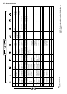
SETPOINTS MENU [2]
ITEM FORMAT UNITS RANGE
0 ±nn.n °C See table below
1 ±nn.n °C See table below
2 nnn °C See table below
3 [1] nnn °C See table below
4 [1] nnn °C See table below
5 nnn % 0 to 100
6 [1] ±nn.n °C/min 0.1 to 1.1
7 [1] ±nn.n °C/min 0.1 to 1.1
8 [1] ±nn.n [3] See table below
9 [1] ±nn.n [3] See table below
10 [1] ±nn.n °C See table below
11 [1] ±nn.n [3] See table below
12 [1] ±nn.n [3] See table below
13 [1] ±nn.n °C -16 to 16
Legend
1 This item is displayed in certain unit configurations only.
2 All points contained in this table can be modified.
* Those setpoints can be used for entering or leaving water temperature control. By default the unit controls the evaporator entering fluid temperature.
Leaving fluid temperature control requires a parameter modification in the Service Configuration menu.
** These parameters are only accessible when reset based on OAT or delta T has been selected in the User Configuration 1 menu. See section 4.5.7.3.
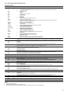
4.5.4 - Description of the Setpoints menu
COMMENTS
This item lets you display and modify Cooling setpoint 1*
This item lets you display and modify Cooling setpoint 2*
This item lets you display and modify Heating setpoint*, only displayed for heat pumps.
This item lets you display and modify the condensing setpoint*. It is used by the control to regulate the fan
stages or a variable-speed fan (air-cooled units) or the condenser water valve control (water-cooled
units), if the unit is not in heat reclaim mode.
This item lets you display and modify the heat reclaim setpoint*. As item 3, this is used for condensing
setpoint control.
Capacity limit setpoint. Limitation by volt-free contact. This item is used to define the maximum capacity
that the unit is authorised to use, if the capacity limit contact activate the limit. See section 5.8.
Cooling ramp loading rate. This parameter is only accessible if the ramp function is validated in the User
Configuration 1 menu. This item refers to the maximum rate of temperature rise in °C in the water heat
exchanger in cooling mode. When capacity loading is effectively limited by the ramp, mode 11 is active.
Heating ramp loading rate. This parameter is only accessible if the ramp function is validated in the User
Configuration 1 menu. This item refers to the maximum rate of temperature drop in °C in the water heat
exchanger in heating mode. When capacity loading is effectively limited by the ramp, mode 11 is active.
Zero reset threshold, cooling mode**
Full reset threshold, cooling mode**
Full reset value, cooling mode**
Zero reset threshold, heating mode**
Full reset threshold, heating mode**
Full reset value, heating mode**
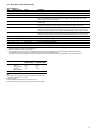
SETPOINT DESCRIPTION CONTROL FOR CONTROL FOR
LEAVING WATER ENTERING WATER
Cooling Minimum setpoint
- Water 3.3°C 9.3°C
- Medium Brine -10°C-4°C
- Low Brine -20°C -14°C
Maximum setpoint
Heating Maximum setpoint MCT - 4.0 MCT - 10.0
Note:
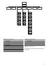
Three setpoint reset configuration modes can be selected in the Client1 menu:
1 Reset using an external 0-10 V d.c. signal
2 Reset using Delta T
3 Reset by external temperature sensor (air-cooled units only)
The items with zero reset or maximum reset are based on these three modes.