


15
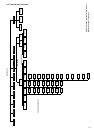
INFORMATION MENU [3]
ITEM FORMAT UNITS
0
±nn.n °C
LOFF -
L-On -
L-Sc -
CCn -
rEM -
MASt -
OFF -
rEADY -
dELAY -
StOPPing -
running -
triPout -
OvErridE -
OCCUPIEd -
UNOCCUPIEd -
COOL -
HEAT -
rECLAIM -
ALArM -
ALErt -
MAStEr -
SLAvE -
1 [1] nn -
2 [2] -
occu
unoc
Forc
3 nn.n minutes
4 [2] -
HEAt -
COOL -
5 [2]
YES -
NO -
6 Nnn %
7 nnn %
8 [2] nnn %
9 [2] nnn
Forc %
10 nnn %
11 [2] -
SP-1
SP-2
AUtO
12 [2] -
occu
unoc
Forc
13 ±nn.n °C
14 ±nn.n
Forc °C
15 ±nn.n °C
16 ±nn.n °C
Forc °C
17 n
18 n
Legend
1 This item is masked when nil.
2 This item is displayed in certain unit configurations only.
3 Access to this menu is read-only except for item 10 that can be forced when the unit is in Local operating type.
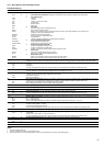
4.5.1 - Description of the Information menu
DESCRIPTION
Automatic display mode. It cycles through the following displays:
1: Controlled water temperature: temperature of the water that the unit tries to maintain at the control point.
2: Unit operating type
Local Off
Local On
Local On - based on unit clock.
CCN Control.
Remote Control
Master unit
3: Unit status
Off: Unit is stopped and not authorised to start.
Ready: Unit is authorised to start
Delay: Unit is in delay at start-up. This delay is active after the unit has been switched on. The delay can be
configured in the User Configuration menu.
Stopping: Unit is currently stopping.
On: Unit is running or authorised to start.
Fault shutdown.
Limit: The operating conditions do not allow total unit operation.
4. Unit occupied/unoccupied status
Occupied: Unit in occupied mode
Unoccupied: Unit in unoccupied mode
5. Heating/cooling operating mode
Cooling: Unit operates in cooling mode
Heating: Unit operates in heating mode
Cooling: Unit is in auto cooling and heat reclaim demand is active
6. Alarm mode
Alarm: Unit is totally stopped because of failure.
Alert: Unit is in failure but not completely stopped.
7. Master/Slave status
Master: The master/slave control is active and the unit is the master
Slave: The master/slave control is active and the unit is the slave
Active mode codes. Each active mode is displayed in turn. This Item is masked when nil. Pressing the enter button when a mode code
is displayed causes a character text expansion to be scrolled accross the four-digit display. See the description in the following table
This item indicates the current chiller occupied/unoccupied mode.
Occupied
Unoccupied
The value is displayed in turn with 'Forc' when the unit is in CCN control and if this variable if forced through CCN.
Start-up delay. This item indicates the minutes left before the unit can be started. This delay at start-up is always active after the unit
has been switched on. The delay can be configured in the User Configuration 1 menu.
Heating/cooling on selection: This item is accessible in read/write, if the unit is in local control mode. It is only displayed, if the unit is
in LOFF, L-On or L-Sc operating type. Displayed for heat pumps.
Heating mode selection
Cooling mode selection
Heat reclaim mode selection: This item is accessible in read/write, if the unit is in local control mode. It is only displayed, if the unit is
in LOFF, L-On or L-Sc operating type. Displayed for air-cooled or water-cooled units with a condenser water valve.
Heat reclaim mode selection, use of heat reclaim condensing setpoint.
Normal cooling mode selection, use of standard condensing setpoint
Total active capacity of unit.
Total active capacity of circuit A.
Total active capacity of circuit B.
Present demand limit. This is the authorised operating capacity of the unit. See section 5.8.
The value is displayed in turn with 'Forc' when the unit is in CCN control and if this variable if forced through CCN.
Present lag chiller demand limit. Displayed when the master/slave control is selected.
Setpoint select in local mode. This point is read/write accessible. Displayed only when the unit is LOFF, L-On or L-Sc operating type.
SP-1 = cooling setpoint 1
SP-2 = cooling setpoint 2
AUtO = active setpoint depends on schedule 2 (setpoint selection schedule). See section 5.7.1 & 4.5.7.6.
Setpoint occupied mode.
Occupied: cooling setpoint 1 is active
Unoccupied: cooling setpoint 2 is active
The value shall be displayed in turn with 'Forc' when the unit is in CCN control and if this variable if forced through CCN.
Active setpoint. This is the current cooling/heating setpoint: it refers to cooling/heating setpoint 1 or 2.
Control point. This is the setpoint used by the controller to adjust the temperature of the leaving or entering water (according to
configuration).
Control point = active setpoint + reset. See section 5.7
The value is displayed in turn with 'Forc' when the unit is in CCN control and if this variable if forced through CCN.
Controlled water temperature. Water temperature that the unit tries to maintain at the control point.
Condensing setpoint. The value is displayed in turn with 'Forc' if the unit is in CCN mode and this parameter is forced by CCN.
Heat reclaim function indicator, circuit A (see heat reclaim section)
Heat reclaim function indicator, circuit B (see heat reclaim section)