


8
SERVICE
Troubleshooting the Drive —
The drive can display
two kinds of error codes on the ICVC called the Alert and
Alarm codes. These codes signal a problem detected during
self tuning or drive operation. Alert and Alarm codes are locat-
ed in the 19XRV Start-Up, Operation and Maintenance Instruc-
tions. Note the following differences between Carrier and
Allen-Bradley terminology:
• A warning message on the ICVC is an ALERT.
• The same warning viewed with Rockwell Drive Explorer
is a VFD ALARM.
• A failure resulting in a shutdown is seen as an ALARM
on the ICVC and as a VFD FAULT when viewed with
Drive Explorer.
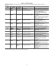
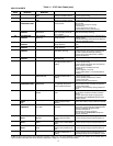
CONDITION CODES
ICVC ALERT = VFD ALARM
ICVC ALARM = VFD FAULT
See Tables 3-6 and Fig. 12.
ICVC ALERT CODES — An alert condition is indicated by
a message at the top of the ICVC default screen. In addition, an
exclamation point (!) will appear next to any affected point on
an ICVC display screen. The drive will continue to operate
during the alert condition. Investigate the cause of the alert to
ensure it does not lead to a fault condition. The alert code will
automatically be cleared from the ICVC when the condition
causing the alert no longer exists. See Table 4.
ICVC ALARM CODES — An alarm condition is also indi-
cated by a message at the top of the ICVC default screen. If an
alarm occurs, the drive coasts to stop. The STS (status) light on
the drive will turn from Green to Red or Yellow (see Table 3).
The detected fault message is maintained on the display until it
is cleared by pressing the RESET softkey. See Table 5.
TEST EQUIPMENT NEEDED TO TROUBLESHOOT —
An isolated multimeter adequately rated for the DC bus volt-
age will be needed to measure DC bus voltage and to make
resistance checks. Note that dedicated troubleshooting test
points are not provided.
WARNING
DC bus capacitors retain hazardous voltages after input
power has been disconnected. After disconnecting input
power, wait five (5) minutes for the DC bus capacitors to
discharge and then check the voltage with a voltmeter to
ensure the DC bus capacitors are discharged before touch-
ing any internal components. Failure to observe this pre-
caution could result in severe bodily injury or loss of life.
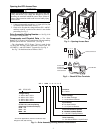
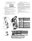
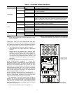
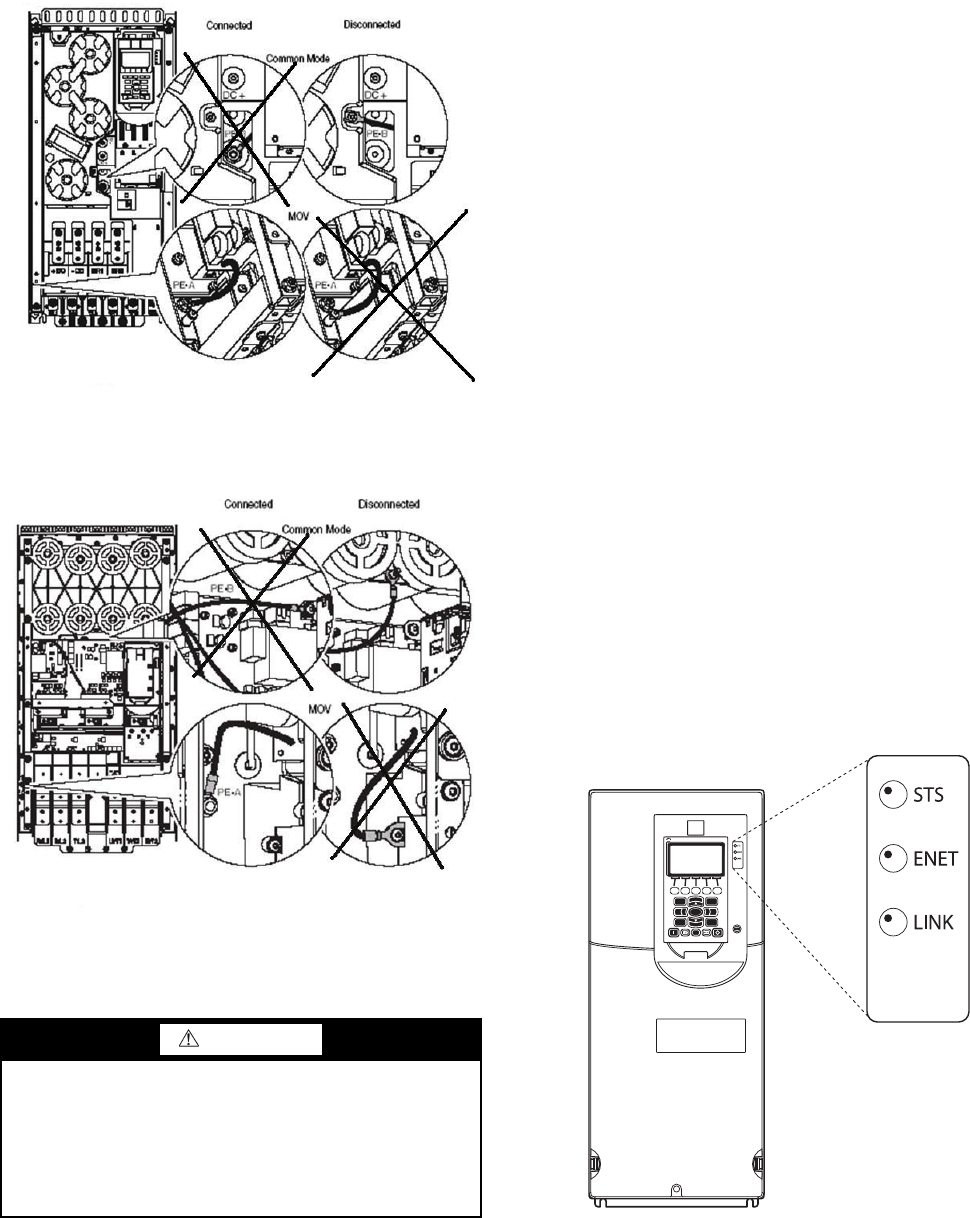
Fig. 11A — Jumper Wire Locations — Frame 6
A19-1835
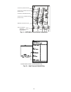
Fig. 11B — Jumper Wire Locations — Frame 7
A19-1836
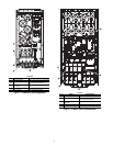
2
8
5
79
13
46
Allen-Bradley
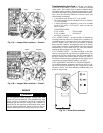
Fig. 12 — Drive Status Indicator
A1
9-
1815